Valve unit fixing structure and fluid pump using the same

a technology of fixing structure and valve unit, which is applied in the direction of valve housing, soldering apparatus, machines/engines, etc., can solve the problems of affecting the supply of inexpensive valve unit fixing structure, requiring time and effort for welding or the like, and a step for controlling deformation, so as to reduce the possibility of transmission of distortion, reduce the number of components, and accurately control the

Active Publication Date: 2019-10-03
HITACHI ASTEMO LTD
View PDF5 Cites 0 Cited by
  • Summary
  • Abstract
  • Description
  • Claims
  • Application Information

AI Technical Summary

Benefits of technology

[0076]This arrangement minimizes the possibility of the transmission of the distortion attributable to the formation of the deformed fixing part to a relief passage, i.e. the relief valve, as described above. Hence, even if the valve seat member of the relief valve is directly press-fitted into the relief passage of the pump main body to fix the valve seat member, the bearing surface of the valve seat member will not be distorted.
[0077]Thu

Problems solved by technology

However, the discharge passage has a high pressure environment therein, and the discharge valve unit must be firmly fixed.
However, according to the foregoing valve unit fixing structures described in Patent Documents 1 and 2, the unitization is performed by welding or the like before the units are fixed to the recesses of the main bodies, thus requiring time and effort for welding or the like or a step for controlling the deformation amount after welding.
These steps interfere with the supply of inexpensive valve unit fixing structures.
Thus, the welding between the valve seat section and th

Method used


Image

  • Valve unit fixing structure and fluid pump using the same
  • Valve unit fixing structure and fluid pump using the same
  • Valve unit fixing structure and fluid pump using the same

Examples


Embodiment Construction

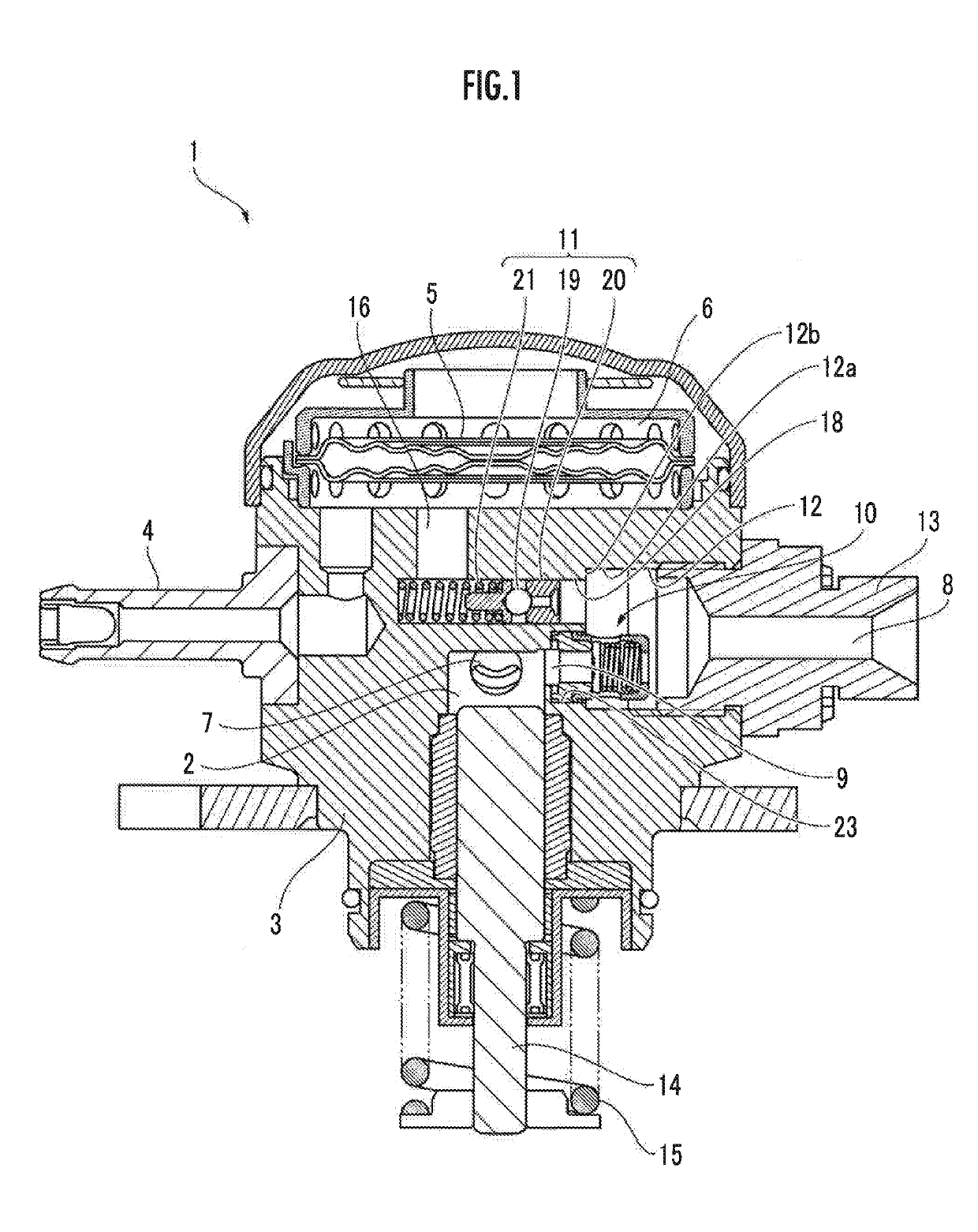
[0084]The embodiments of the present invention will now be described with reference to the accompanying drawings. FIG. 1 illustrates an essential section of a high-pressure fuel pump in a fuel supply system of a direct-injection engine according to an embodiment of the present invention. The high-pressure fuel pump increases the pressure of a fuel fed from a fuel tank by using the rotative power of an engine cam and supplies the fuel to an injector.

[0085]Referring to FIG. 1, a high-pressure fuel pump 1 includes a main body 3 serving as a pump main body having a compression chamber 2. The compression chamber 2 is used to suck in a fuel as a fluid fed from a fuel tank, increase the pressure of the fuel and then discharge the fuel. The fuel is supplied to the compression chamber 2 through a damper chamber 6, in which a pulsation damper 5 is placed, and an intake port 7 from an intake pipe 4 connected to a low-pressure fuel pump of the fuel tank.

[0086]The main body 3 is provided with a ...


PUM

PropertyMeasurementUnit
Pressureaaaaaaaaaa

Abstract

The present invention provides an inexpensive valve unit fixing structure that enables a valve unit to be easily fixed without the need for unitization in advance, and a fluid pump that enables a discharge valve and a relief valve to be incorporated in a compact manner. The valve unit fixing structure includes a main body (3), a discharge communication passage (9) provided inside the main body (3), a discharge valve unit (10) which is provided in the main body (3) and which opens/closes the discharge communication passage (9), and deformed fixing parts (35) which are formed by plastically deforming the main body (3) and which fix the discharge valve unit (10) to the main body (3).

Description

BACKGROUND OF THE INVENTION1. Field of the Invention[0001]The present invention relates to a valve unit fixing structure in which a valve unit is fixed to a main body, and a fluid pump using the same.2. Description of the Related Art[0002]Hitherto, there has been known a valve unit fixing structure that includes a valve unit and a main body to which the valve unit is fixed (refer to, for example, Patent Documents 1 and 2). The main body includes a main body flow passage which is provided inside the main body and through which a fluid passes, and a recess having the bottom part thereof in communication with the main body flow passage. The valve unit includes a valve seat section having a valve seat, a valve body which comes in contact with the valve seat to close the main body flow passage, a spring member which urges the valve body toward the valve seat section, and a holder which accommodates the spring member.[0003]According to the valve unit fixing structure described in Patent D...

Claims


Application Information

Patent Timeline
IPC IPC(8): F16K17/04F16K15/02F16K27/02
CPCF16K15/025F16K27/0209F16K17/0406F16K25/00F02M59/46F02M59/462F16K15/028F02M59/44B23K1/0006
Inventor KANEKO, YOHEIOGANE, YUYA
Owner HITACHI ASTEMO LTD
Why Eureka
Try Eureka