Remote control system for a vehicle

a remote control and vehicle technology, applied in the field of remote control systems for vehicles, can solve the problems of user verification of doors, high difficulty, and inability to perform door locking, and achieve the effects of reducing power consumption, reducing the transmission of response demand signals, and improving the anti-thief function

Inactive Publication Date: 2006-02-14
HONDA MOTOR CO LTD
View PDF9 Cites 28 Cited by
  • Summary
  • Abstract
  • Description
  • Claims
  • Application Information

AI Technical Summary

Benefits of technology

[0030]More particularly, while the portable transmitter / receiver is out of the largest predetermined receivable range, the response demand signal receivable in the largest predetermined range only is transmitted. Only when the response signal responding to the response demand signal receivable in the largest predetermined range is received by the vehicle, the transmission of the response demand signal being receivable in a smaller size of the predetermine range and used for actually controlling the unlocking and locking of the door is executed. Therefore, the transmission of the response demand signal is minimized hence reducing the consumption of a power from a battery equipped on the vehicle.
[0031]According to the seventh feature of the present invention, the user carrying the portable transmitter / receiver in the vehicle can readily be acknowledged, and the vehicle mounted device in the vehicle is controlled on the basis of the response signal from the portable transmitter / receiver responding to a particular type of the response demand signal receivable within the vehicle, hence improving the anti-thief function.

Problems solved by technology

However, as the communication area is wide, the locking of the door will be carried out only when the user departs further from the vehicle, hence causing the user to confirm the door locking (through listening to the sound of the door locking mechanism or viewing the shift of the inside door lock knob to the lock position) with much difficulty.
Also, while the user with the entry key walks about or pursues a job (e.g. ordering throughout the trunk room), the door locking is not performed and it may fail to protect articles in the vehicle from a thief.
The wider the predetermined communication area, the longer the period of the door remaining unlocked is extended and thus the higher the risk of being thieved will be increased.
Also, the wider communication area requires a higher level of power for transmitting the response demand signal and the power consumption will be soared up drawing more power from the battery.
However, the above modification will hardly ensure the unlocking of the door.
With the smaller communication area, however, when the user rushes to the vehicle in less time through the communication area, the communication between the vehicle-mounted transmitter and the entry key may not be completed until the user arrives at the vehicle.
This causes the door to remain locked and its door outer handle may have to be operated a number of times without success.
As a result, the entry key system will be lost in commercial value.
This will however increase the power consumption and cause more power be drawn from the battery.
On the other hand, the conventional system disclosed in the above-mentioned Japanese Patent Laid-open Publication (Heisei)10-153025 allows the power for transmitting the response demand signal to be possibly decreased, but it requires the extra transmission antenna for detecting the invading of an object, hence increasing the complexity of the overall arrangement and thus the cost of the system.
Also, the power consumption will be increased by the additional equipment.
Moreover, the above system transmits the response demand signal even when any other personal or creature than the right entry key (user) advances close to the vehicle, hence requiring more improvement for the power consumption.
This will result in the misconduct of the automatic unlocking function.

Method used


Image

  • Remote control system for a vehicle
  • Remote control system for a vehicle
  • Remote control system for a vehicle

Examples


Embodiment Construction

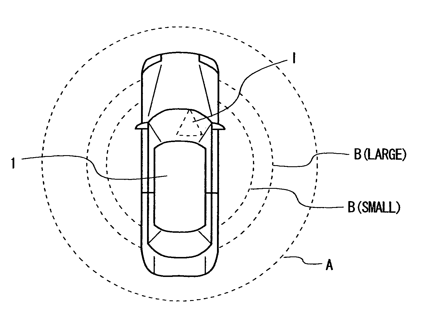
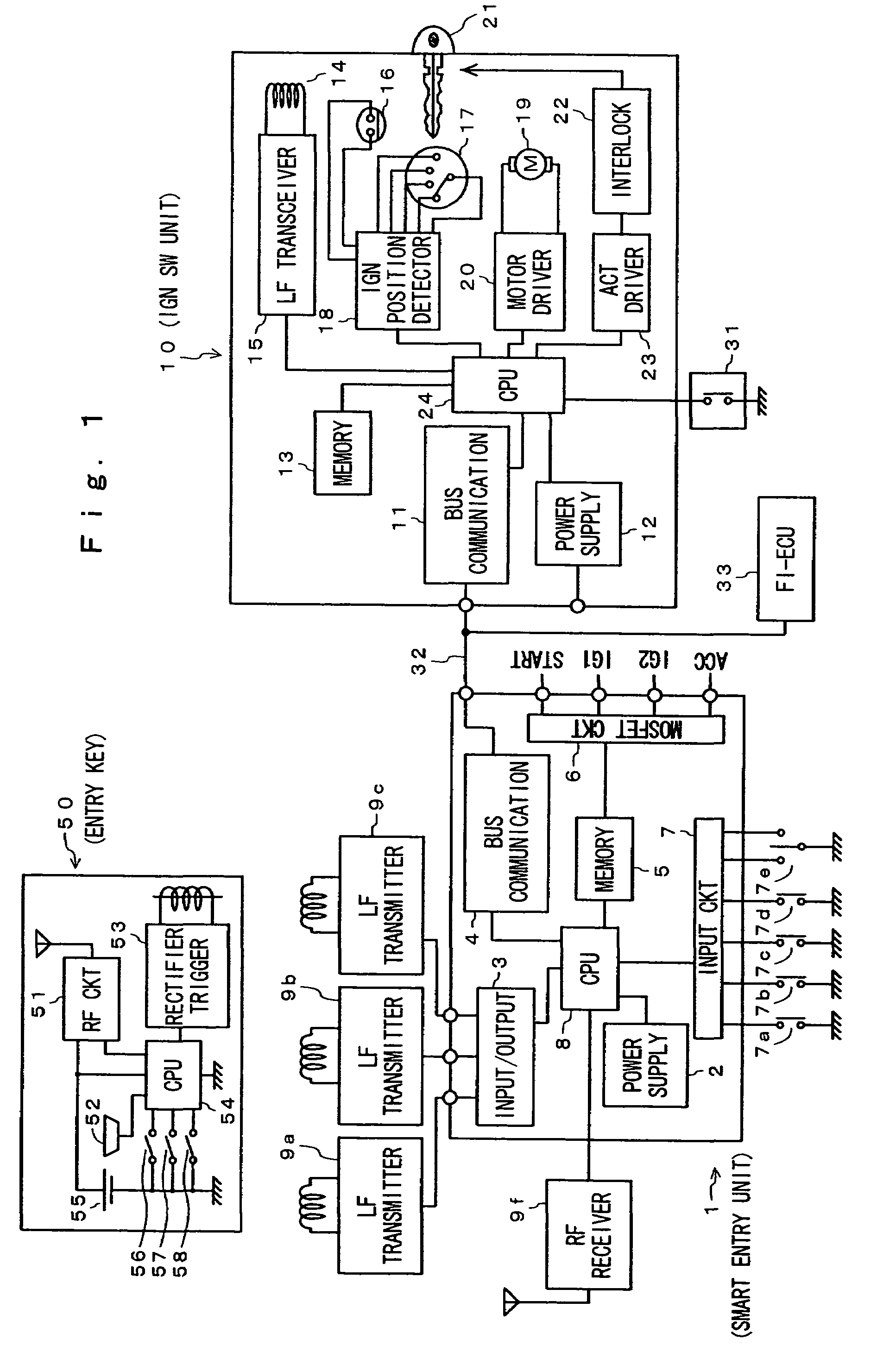
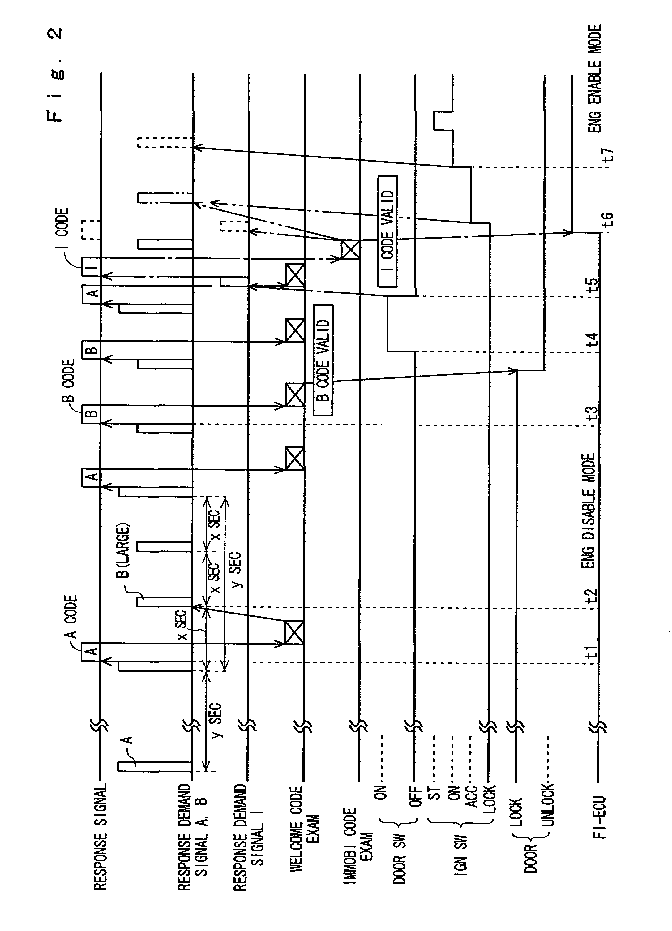
[0056]An entry key system for a vehicle according to first embodiment of the present invention will be describe in more detail referring to the accompanying drawings. Before starting the main description, some definitions on the flags at 1 of the bit and the timers employed in the description and the drawings are explained as listed below.[0057]AREC=reception of A code;[0058]ATM=transmission of A response demand signal;[0059]BCHG=start of examining the shift from small B response demand signal to large B response demand signal;[0060]BLTM=transmission of large B response demand signal;[0061]BREC=reception of B code;[0062]BSTM=transmission of small B response demand signal;[0063]I(variable)=the number of consecutive receptions of A code;[0064]IMCHK=start of immobilizing checkup;[0065]IMDONE=finish of immobilizing checkup;[0066]IMOK=result of immobilizing checkup;[0067]m(variable)=setting in timer T-OUT;[0068]MOD(n,m)=remainder of n / m;[0069]n(variable)=setting for the kind of response ...


PUM


Abstract

A remote control system for precisely identifying a distance from the vehicle to an entry key and favorably controlling a vehicle-mounted device such as a door corresponding to the distance. The system comprises a transmitter transmitting different types of response demand signals within a predetermined communication area outside the vehicle, a vehicle mounted receiver for receiving a response signal released from a portable transmitter/receiver in response to the reception of the response demand signal, a controller controlling the vehicle mounted device corresponding to the reception of the response signal by the vehicle mounted receiver. Locking and/or unlocking door(s) of the vehicle are controlled on the basis of whether or not the receiver receives the response signal to a response demand signal other than one having the largest communication area.

Description

[0001]This application is a continuation of prior application Ser. No. 09 / 612,315 filed Jul. 7, 2000, now U.S. Pat. No. 6,778,065.BACKGROUND OF THE INVENTION[0002]1. Field of the Invention[0003]The present invention relates to a remote control system for a vehicle which can automatically lock and unlock the door(s) of a vehicle in wireless communication and more particularly to a remote control system for a vehicle which can automatically lock the door(s) of a vehicle when a user (driver) who carries with him an electronic or entry key (with a portable transmitter / receiver) which includes an identification code assigned to the vehicle walks away a predetermined distance from the vehicle and automatically unlock the same when the user comes back to the distance.[0004]2. Description of the Related Art[0005]Lock / unlock remote-control systems for vehicle doors are known having a so-called, “welcome function”. In the systems, every user (driver) of a vehicle owns an entry key (with a por...

Claims


Application Information

Patent Timeline
Patent Type & Authority Patents(United States)
IPC IPC(8): G05B19/00E05B49/00E05B83/36G07C9/00
CPCB60R25/245G07C9/00309G07C2209/63
Inventor ASAKURA, SUGURUNAGAI, AKIRAYOSHIMURA, KENTARONOZAWA, MUNEHISAWATARAI, SADANORI
Owner HONDA MOTOR CO LTD
Why Eureka
Try Eureka