Imaging device

a compact, imaging technology, applied in the direction of printers, cameras, instruments, etc., can solve the problems of deteriorating the response of the actuator to the driving operation during cooling, affecting the performance of the actuator, and hardly allowing flexibility for setting the mounting position on the printed board. , to achieve the effect of improving the response rate, improving the heat release property of the shape-memory actuator, and small wiring structur

Inactive Publication Date: 2012-03-20
MAXELL HLDG LTD
View PDF7 Cites 1 Cited by
  • Summary
  • Abstract
  • Description
  • Claims
  • Application Information

AI Technical Summary

Benefits of technology

[0005]It is an object of the present invention to provide a highly reliable camera module provided with an actuator which allows size reduction of the camera module.
[0007]In the actuator device of the camera module according to the invention, one end of the metal pin is electrically connected to an electric wiring pattern formed on the printed circuit board via an adhesive agent as a solder so as to apply the drive current from the printed circuit board to the shape-memory actuator. Heat generated by the shape-memory actuator is thermally conducted to the printed circuit board via the metal pin and the solder each serving as a good thermal conductor. The shape-memory actuator may exhibit good heat release property and reduce the wiring size.
[0009]In the actuator device of the camera module, one end of the metal pin is thermally connected to the plate spring. The heat generated by the shape-memory actuator is thermally conducted to the plate spring via the metal pin serving as the good thermal conductor. The shape-memory actuator may exhibit improved heat release property.
[0012]In the actuator device of the camera module according to the invention, each of the lens holder and the support beam exhibits good thermal conductivity.
[0016]In the camera module as the imaging device according to the invention using the shape-memory actuator of general current application heat type, the response speed is regulated in accordance with the heat release rate of the shape-memory actuator. The joint portion between the shape-memory actuator and the electrode for current application has a large difference of the expansion rate upon current application, thus causing the contact failure. The conductive metal pin is press fit into the groove structure through which the actuator is inserted so as to allow electric contact between the metal pin and the shape-memory actuator. This may allow the actuator to be fixed to the casing.
[0017]One end of the metal pin is electrically connected to the electric wiring pattern formed on the printed circuit board via the adhesive agent such as the solder. The compact mount of the shape-memory actuator with small wiring structure may be realized. Furthermore, the heat generated by the shape-memory actuator is thermally conducted to the printed circuit board via the metal pin serving as a good heat conductor and the solder to realize improved heat release property of the shape-memory actuator, thus improving the response rate.

Problems solved by technology

The aforementioned structure is so complicated that the size reduction is limited, resulting in disadvantage of cost increase.
The related art disclosed in Japanese Unexamined Patent Application Publication No. 2003-111458 is not provided with a mechanism for cooling the actuator, thus deteriorating the response of the actuator to the driving operation during cooling.
Direct fixation between the actuator and the printed circuit board via a solder hardly allows flexibility for setting the mount position on the printed board.
Under the heat resulting from current application to the actuator causes thermal expansion of the actuator, thus deteriorating the contact between the actuator and the solder.
The heat release of the shape-memory actuator is deteriorated to impair the response during cooling.
The temperature of the image pickup device is also increased to raise noise level, resulting in deteriorated image quality.

Method used


Image

  • Imaging device
  • Imaging device
  • Imaging device

Examples


first embodiment

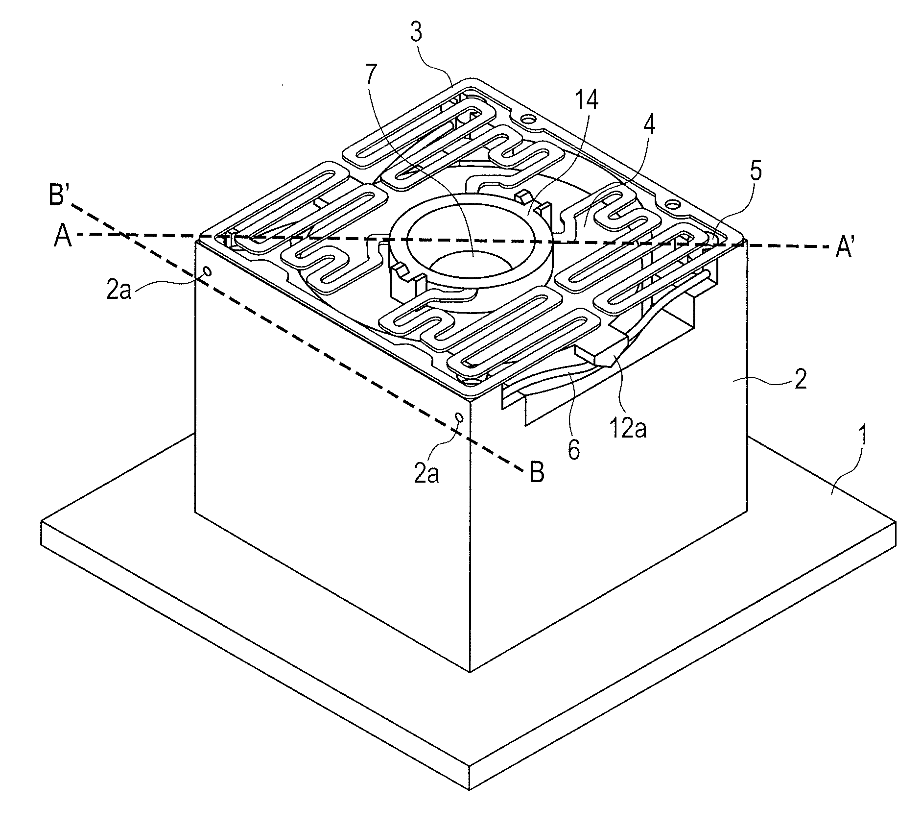
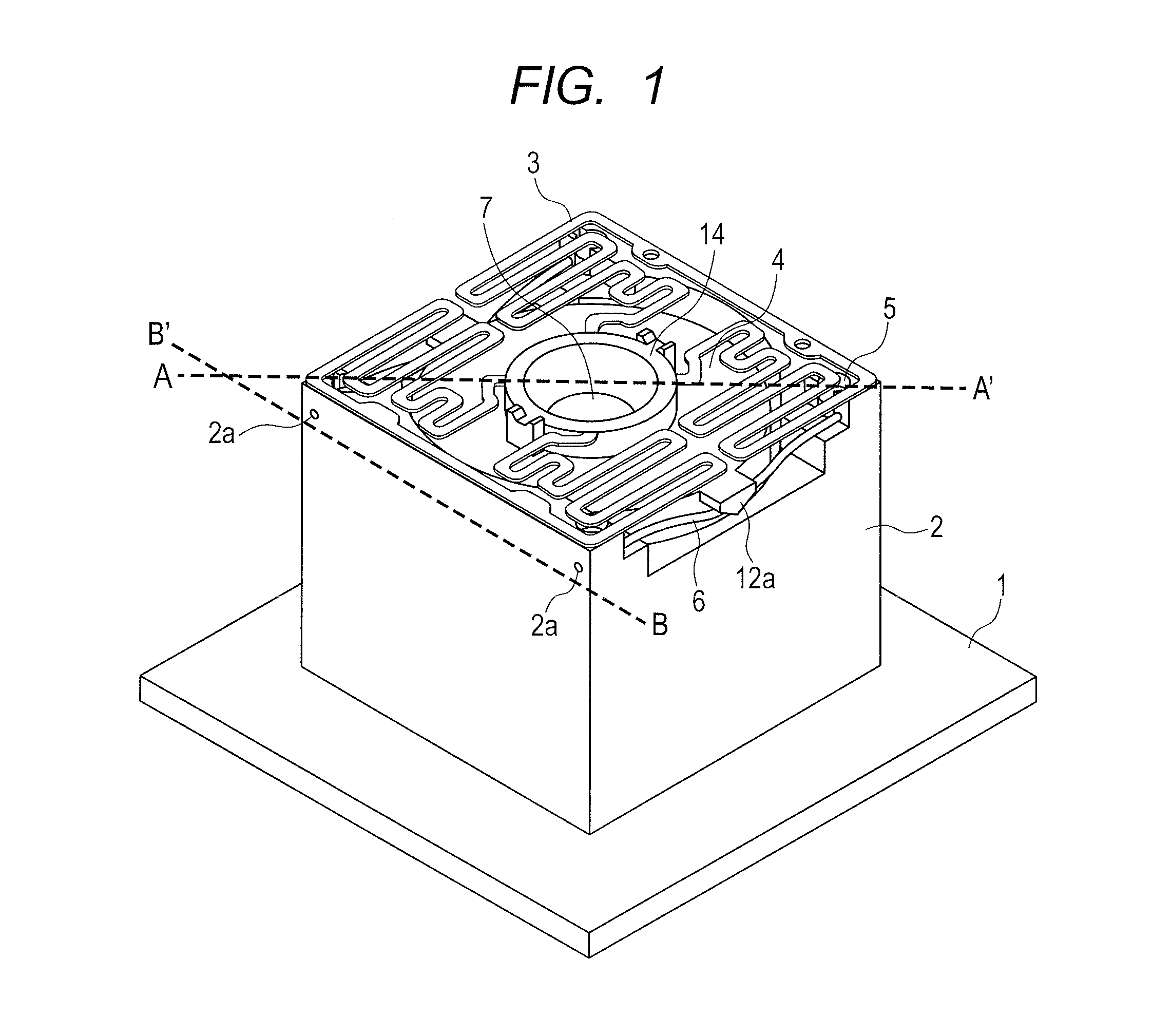
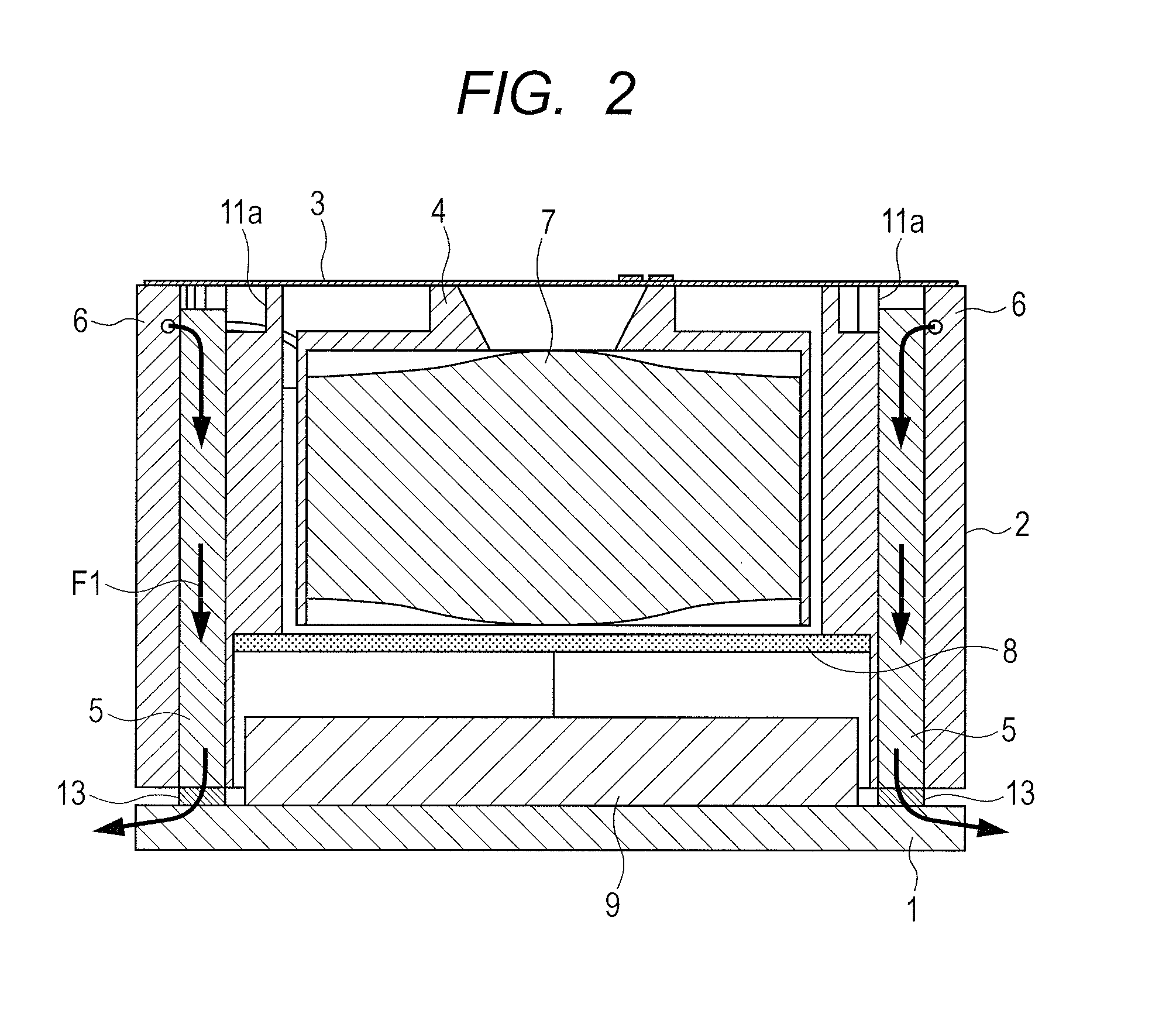
[0031]FIG. 1 is an explanatory view illustrating a basic structure of a camera module according to a first embodiment of the invention. FIG. 2 is an explanatory view of a vertical section of the structure shown in FIG. 1 taken along a broken line A-A′. FIG. 3 is an explanatory view of a horizontal section of the structure shown in FIG. 1 taken along a broken line B-B′. FIG. 4 is an enlarged view of a region R1 enclosed by a broken line shown in FIG. 3.

[0032]FIG. 1 illustrates a printed circuit board 1, a camera casing 2, an insertion hole 2a of a shape-memory actuator wire, a plate spring 3 for pressurizing a lens holder, the lens holder 4 for fixing a lens 7, and a metal pin 5 which serves to fix a shape-memory actuator 6 while functioning as a conductor wire. FIG. 2 illustrates an infrared filter 8, an image pickup device 9, a solder 13 for bonding the metal pin and the printed wiring, and a flow F1 of the heat generated by the shape-memory actuator 6. FIG. 4 illustrates a contact...

second embodiment

[0038]A second embodiment will be described.

[0039]The heat release means of the second embodiment is different from that of the first embodiment. The different structure will be described hereinafter.

[0040]In the second embodiment, the metal pin 5 and the plate spring 3 according to the first embodiment shown in FIG. 2 are thermally connected. The solid line L1 of FIG. 6 according to the first embodiment indicates the response expressed by the relationship between the temperature and time. Meanwhile, the shape-memory actuator 6 transfers and releases the generated heat to the plate spring 3 as the good thermal conductor via the metal pin 5 in addition to the general heat release only from the printed circuit board 1 via the metal pin 5 to improve the heat release property. Accordingly, the response rate of the actuator may be improved as shown by the broken line L2 of FIG. 6. The heat transferred to the plate spring 3 is brought into contact with ambient air while being released.

[00...

third embodiment

[0042]A third embodiment will be described.

[0043]The actuator of the third embodiment is different from that of the first and the second embodiments. The arrangement and outer appearance of the structure according to the third embodiment are substantially the same as those of the first embodiment. However, the shape-memory actuator 6 is configured to expand and contract under the electric field generated by voltage application, for example, as an ion conduction polymer actuator. It has such feature as small heat generation amount, requiring no consideration with respect to the heat release.


PUM


Abstract

A metal pin is inserted into a hole cylindrically formed in a camera casing so as to be in contact with a shape-memory actuator. The metal pin and the shape-memory actuator are fixed by pressurization. The metal pin is further bonded to a printed circuit board via a solder to electrically and thermally contact the shape-memory actuator and the printed circuit board so as to form the camera module by reducing the wiring size and improving the cooling efficiency.

Description

TECHNICAL FIELD[0001]The present invention relates to a compact imaging device installed in a mobile phone and the like for use.BACKGROUND ART[0002]Generally, a compact camera module installed in the mobile phone for use is structured to drive a lens using a stepping motor, a voice coil motor and a piezoelectric motor for the purpose of adjusting focus and changing a magnification percentage. The aforementioned structure is so complicated that the size reduction is limited, resulting in disadvantage of cost increase. A compact camera module is disclosed in Japanese Unexamined Patent Application Publication No. 2003-111458, which employs a shape-memory actuator with simple structure and compact size for cost reduction. The aforementioned actuator is structured to bring a center curved portion of the U-like shape-memory-alloy in contact with a lens guide portion provided at one side of a lens holder, and slidably move the lens holder along the guide under the heat resulting from curre...

Claims


Application Information

Patent Timeline
Patent Type & Authority Patents(United States)
IPC IPC(8): G03B3/10G02B7/04
CPCG02B7/08H04N5/2257H04N5/2252G02B13/001H04N23/57H04N23/51G03B30/00
Inventor HASHIZUME, JIROSHINTA, IKUOYAMAUCHI, YOSHIAKI
Owner MAXELL HLDG LTD
Why Eureka
Try Eureka