Coupling

a technology of coupling and radial load, applied in the direction of slip coupling, agricultural machines, gearing, etc., can solve the problems of conventionally poor support of radial load and conventional poor support of couplings to transmit high torque, and achieve the effect of reducing the load and reducing the lifetim

Active Publication Date: 2020-03-03
BLUE LEAF I P INC
View PDF15 Cites 0 Cited by
  • Summary
  • Abstract
  • Description
  • Claims
  • Application Information

AI Technical Summary

Benefits of technology

[0007]In the claimed invention, the coupling comprises a first connection and a second connection. This is based on the insight that a coupling that accommodates a misalignment is conventionally very poor in supporting a radial load. Furthermore, couplings to transmit a high torques are conventionally very poor in accommodating a misalignment. When such coupling is adapted to accommodate a misalignment and is able to support a radial load, the misalignment induces a radial torque to the shafts thereby wearing off the teeth of the supplying connection. Thereby radial torque is defined as a torque exerted around an axis which shows an angle with respect to the rotation axis of the shaft. The coupling of the invention solves this problem by providing a dual connection. The first connection is formed by the fourth bearing which is adapted to support the radial load, so that the second connection is free from radial loads. This allows the second connection to be adapted to transmit a torque and to accommodate a misalignment without inducing a radial torque to the shafts. Because misalignment is accommodated by both the first and the second connection, without inducing a significant radial torque to the shafts, the coupling can operate and support a radial load and transmit high torques without damaging the shafts.
[0018]Preferably, the industrial work vehicle is an agricultural vehicle. Further, preferably, the frame is a pick-up frame, the first shaft is a pick-up drive shaft and the second shaft is a packer drive shaft. The invention is arisen to solve significant wear problems to pick drive shafts and packer drive shafts. The pick drive shaft is connected to the packer drive shaft as is described above via a coupling. Any misalignment of the one shaft with respect to the other shaft, in a prior art setup, induces a significant wear to the splines provided at the shafts so that the shafts have a shortened lifetime. This problem was solved by implementing a shaft as is described above.

Problems solved by technology

This is based on the insight that a coupling that accommodates a misalignment is conventionally very poor in supporting a radial load.
Furthermore, couplings to transmit a high torques are conventionally very poor in accommodating a misalignment.

Method used


Image

  • Coupling
  • Coupling
  • Coupling

Examples


first embodiment

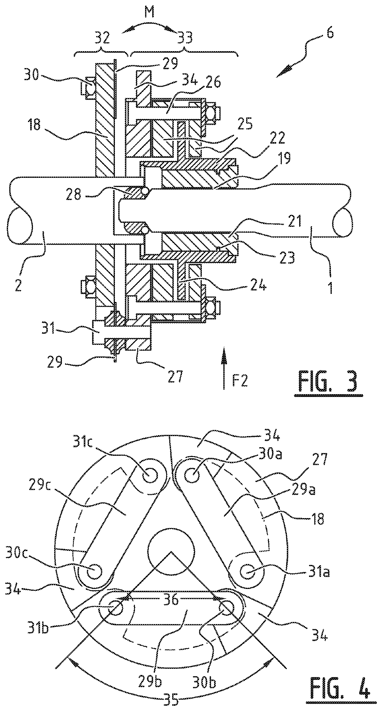
[0046]The assembled coupling of the first embodiment, as is shown in FIG. 3 comprises a first part 33 at an end of the first shaft 1, and comprises a second part 32 at an end of the second shaft 2. An axial torque can be transmitted from the first part 33 to the second part 32 via the spring plates 29. A radial load F2 can be supported by the fourth bearing 28. Movements M resulting from a misalignment between the first shaft 1 and the second shaft 2 are accommodated by both the fourth bearing 28 which is preferably spherical, and by the spring plates 29 as is described above. The effect is that movements resulting from a misalignment are allowed in the coupling 6 with a minimal resistance so that no significant radial torque forces arise. This significantly decreases the wear on the spline connection 19.

second embodiment

[0047]FIGS. 5 and 6 show the invention, wherein the segment of the coupling between the first flange element 27 and the first shaft 1 is substantially identical to the embodiment of FIG. 3. Therefore a description of this part is omitted and reference is made to the description above.

[0048]In the embodiment of FIG. 5 a spring plate 29 is provided that comprises the first connection 28 in a central part of the coupling 6 and the second connection at the periphery of the coupling 6. Particularly, the spring plate 29 comprises a central opening wherein the second shaft 2 is inserted. By this insertion of the second shaft 2 in the central opening of the spring plate 29, radial loads F2 can be supported. Furthermore, the spring plate 29 is provided at its periphery with multiple protrusions. There protrusions are best illustrated in FIG. 6. Each of the protrusions corresponds to a location or corresponding location at the first or second flange element. In the embodiment of FIG. 5, bendi...

third embodiment

[0050]FIG. 7 shows the invention, wherein the coupling part between the first shaft 1 and the first flange element 27 is identical to the previous embodiments. The coupling comprises a first connection 28 formed by a fourth bearing located in the central part of the coupling, and comprises a second connection at the periphery of the coupling, which is in the embodiment of FIG. 7 formed by a spherical spline connection 39. The fourth bearing 28 is also formed as a spherical bearing 28, so that the fourth bearing can support a radial load and accommodate a misalignment of the first shaft 1 and the second shaft 2. An inner part of a spherical spline 37 is connected to the second shaft 2. This inner part 37 is connected to an outer part 38 of a spherical spline. This outer part 38 forms a flange 40 that is rigidly connected to the first flange 27. Tolerances of the fourth bearing 28 and the spline connection 39 are designed such that at least the majority of a radial load is supported b...


PUM


Abstract

An industrial work vehicle including a frame and a first shaft rotatably connected to the frame via first and second bearings. The work vehicle further includes a second shaft rotatably positioned in line with the first shaft and connected to the first shaft via a coupling. The second shaft is further connected to the frame via a third bearing. The coupling includes a first connection and a second connection. The first connection connects the first shaft to the second shaft via a fourth bearing adapted to support a radial load and to accommodate an axial rotation and an angular misalignment of one shaft with respect to the other shaft. The second connection connects the first shaft to the second shaft via flange elements which are interconnected via an intermediary element adapted to transmit a torque and to accommodate a misalignment of one shaft with respect to the other shaft.

Description

CROSS REFERENCE TO RELATED APPLICATION[0001]This application claims priority to Belgium Application No. 2016 / 5121 filed Feb. 22, 2016, the contents of which are incorporated herein by reference.FIELD OF THE INVENTION[0002]The present invention relates to an industrial work vehicle comprising a frame and a first shaft rotatably connected to the frame via a first and a second bearing support, the work vehicle further comprising a second shaft rotatably positioned in line with the first shaft and connected to the first shaft via a coupling, and the second shaft being further connected to the frame via a third bearing support.BACKGROUND OF THE INVENTION[0003]Such combination of shafts is often used in industrial work vehicles to synchronize two movements. A first movement is directly related to the first shaft and a second movement is directly related to the second shaft. Thereby, one of the two shafts is typically driven, and the other of the two shafts is connected to one of the shaft...

Claims


Application Information

Patent Timeline
Patent Type & Authority Patents(United States)
IPC IPC(8): F16D3/78F16D3/60A01D89/00B60K25/02F16D7/02A01B61/02F16D41/00F16H7/02
CPCB60K25/02A01B61/025A01D89/005F16D3/78F16D3/60F16D7/025F16D41/00B60K2025/022F16H7/02
Inventor BONTE, XAVIERGRYSON, RUBEN
Owner BLUE LEAF I P INC
Why Eureka
Try Eureka