Catheter support structure

a support structure and catheter technology, applied in the field of catheters, can solve the problems of catheters catheters may be subjected to closure or geometric deformation, and catheters may be subjected to high internal pressure, etc., to achieve enhanced torque and axial load transmission

Inactive Publication Date: 2001-09-18
EV3 PERIPHERAL
View PDF25 Cites 62 Cited by
  • Summary
  • Abstract
  • Description
  • Claims
  • Application Information

AI Technical Summary

Benefits of technology

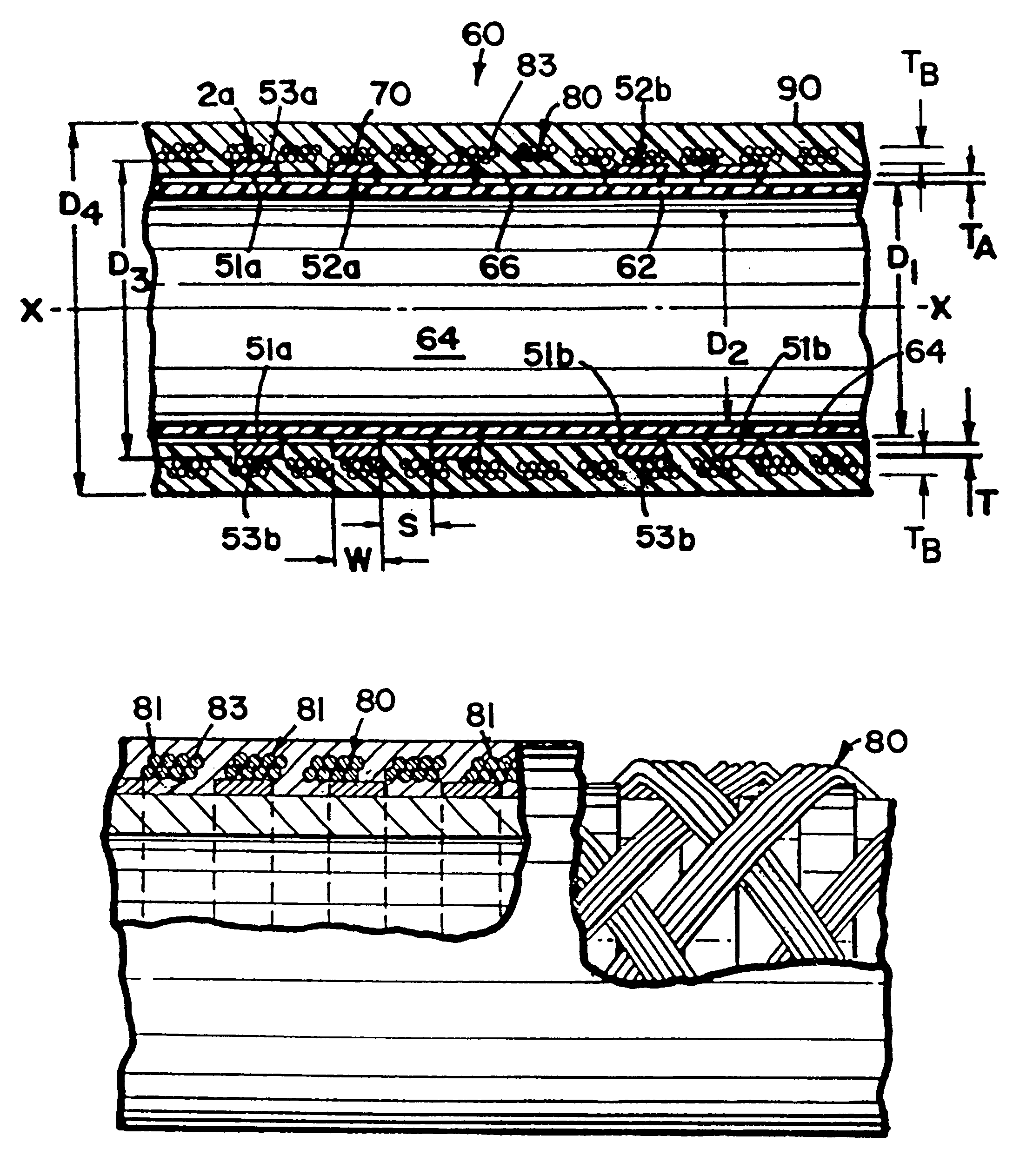
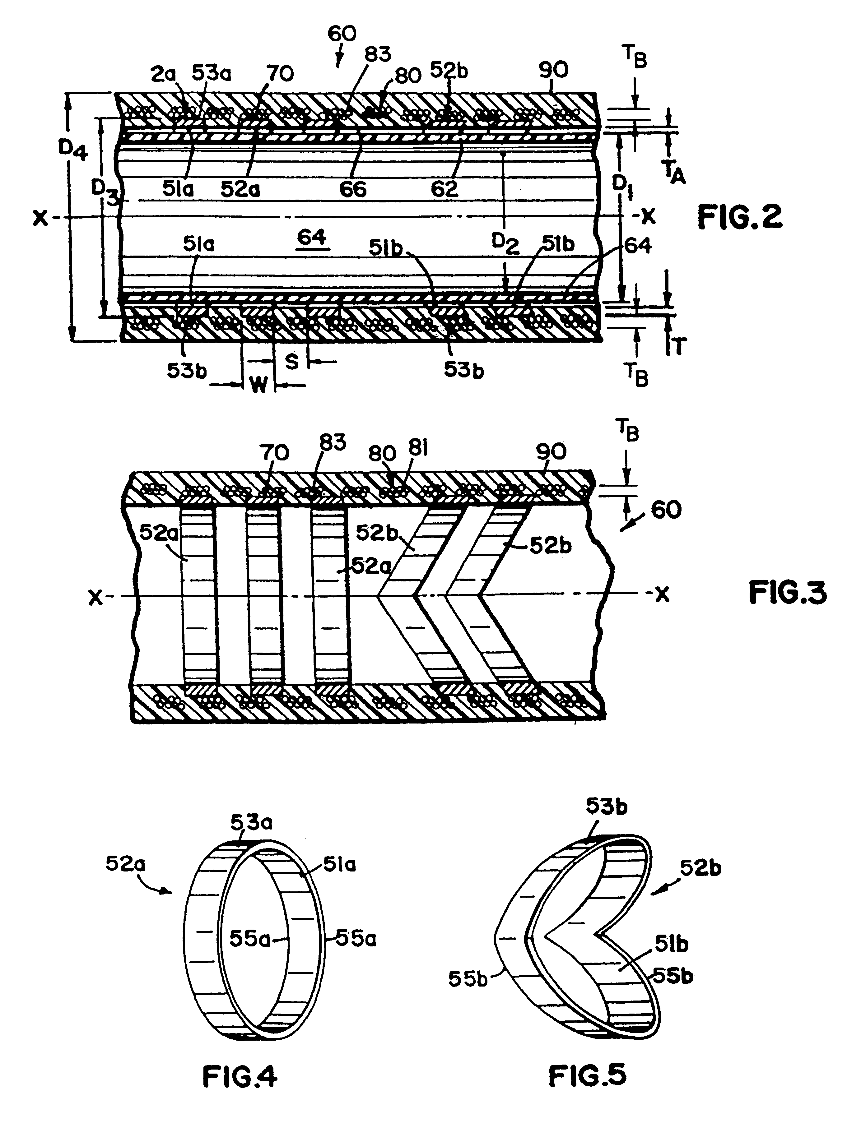
One aspect of the present invention relates to a catheter including a segment having a longitudinal axis, and a plurality of circumferential supports surrounding the axis. A plurality of filaments surround the circumferential supports. The circumferential supports assist in providing kink resistance, while the filaments provide enhanced torque and axial load transmission through the catheter segment.

Problems solved by technology

When a catheter bends, it may be inclined to kink resulting in closure or geometric deformation of the circular bore.
Such closure or deformation is undesirable.
Further, in certain applications, the catheter may be subjected to high internal pressures (e.g., 300 psi).
Such pressures tend to burst the catheter or expand the catheter geometry.
Unfortunately, such catheters are costly and have an extra layer of coil which takes up an already limited space within the vasculature.

Method used


Image

  • Catheter support structure
  • Catheter support structure
  • Catheter support structure

Examples


Embodiment Construction

Referring now to the several drawing figures in which identical elements are numbered identically throughout, a description of a preferred embodiment of the present invention will now be provided.

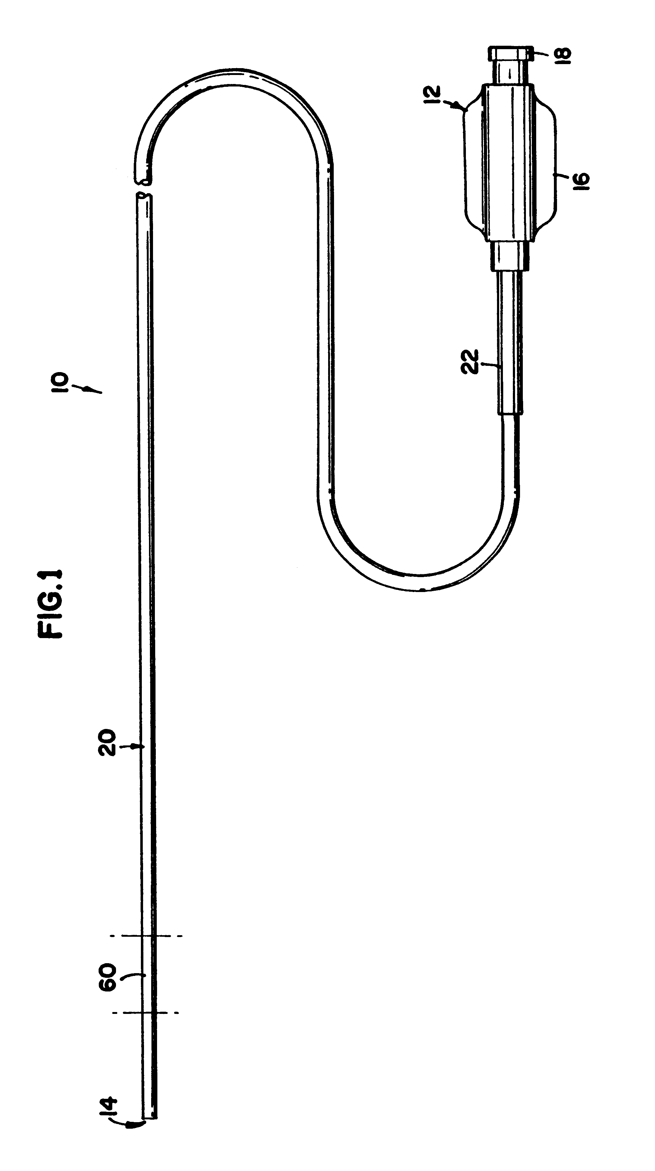
FIG. 1 illustrates a catheter 10. The catheter 10 extends from a proximal end 12 to a distal end 14. At the proximal end 12, a hub 16 is provided to be gripped by a physician as well as having an inlet 18 for injection of fluids into the catheter 10. A flexible hollow shaft 20 is connected to the hub 16. The shaft 20 is sized to be inserted into a patient's vasculature. The shaft 20 is commonly about 150 cm long. A strain relief jacket 22 connects the shaft 20 to the hub 16. The foregoing description forms no part of this invention and is given to facilitate an understanding of the present invention.

The catheter 10 includes a segment 60 having the novel construction of the present invention. (For purposes of the remainder of this description, the word "catheter" is generally used to refer t...


PUM


Abstract

The present disclosure relates to a catheter including a segment having a longitudinal axis, and a plurality of circumferential supports surrounding the axis. A plurality of filaments surround the circumferential supports to enhance torque transmission through the catheter segment.

Description

I. BACKGROUND OF THE INVENTION1. Field of the InventionThis invention pertains to catheters for passage through a vasculature system. More particularly, this invention pertains to a novel construction of at least a segment of a catheter.2. Description of the Prior ArtCatheters are widely used in medical treatment. A catheter is an elongated flexible member advanced through the vasculature system to a desired site. The catheter may be advanced over a previously inserted guide wire.With the catheter in place, a wide variety of substances may be passed through the catheter to the site. For example, drugs may be moved through the catheter for site-specific drug delivery. Also, implements may be passed through the catheter. The catheter may also be used to remove fluids from the site. Still further, a catheter may be equipped with implements (e.g., balloon tips) for performing procedures (e.g., angioplasty) at the site.Catheters have long been used in cardiovascular treatment. More recen...

Claims


Application Information

Patent Timeline
Patent Type & Authority Patents(United States)
IPC IPC(8): A61M25/00A61M25/16
CPCA61M25/0054A61M25/0052
Inventor KLIMA, DANIEL J.THOMPSON, PAUL J.
Owner EV3 PERIPHERAL
Why Eureka
Try Eureka