Helical interlocking mating guide and advancement structure

a technology of interlocking mating and guide, which is applied in the direction of prosthesis, ligaments, osteosynthesis devices, etc., can solve the problems of implant design, implant failure, and surgeons installing implants, and achieve the effects of reducing the likelihood of implant and closure system failure during use, high torque, and relatively economic formation

Inactive Publication Date: 2006-01-12
JACKSON
View PDF99 Cites 68 Cited by
  • Summary
  • Abstract
  • Description
  • Claims
  • Application Information

AI Technical Summary

Benefits of technology

[0037] Therefore, objects of the present invention include: providing an improved closure for an open headed lightweight and low profile medical implant wherein the implant has a pair of spaced arms and the closure closes between the arms; providing such a closure which includes a pair of opposed interlocking forms and which resists tendencies of the arms to splay or separate during insertion of the closure, to thereby reduce the likelihood of failure of the implant and closure system during use; providing such a closure which can be installed at comparatively high torques to thereby secure the closure in the receiver channel and in certain embodiments to also lock a rod member in the open head of the implant where the closure engages and is urged against the rod by rotation in a receiver channel of the remainder of the implant; providing an interlocking form for such a closure which resists tendencies of parts of the channel receiver to expand radially outward in response to high torque applied to the closure; providing such an interlocking form in which the respective thrust surfaces of mating internal and external interlocking forms are “non-linear”, compound, or complex to provide only a portion of each trailing or leading surface which is oriented in such a direction as to resist the splaying or expanding tendencies of parts of the receiving channel; providing such an interlocking form wherein the interlocking form has a base that is secured to a member and the interlocking form extends radially outward from the base with an axial extension starting at or radially spaced from the base and further wherein the interlocking form has an extension or depression that extends in an axial direction relative to an axis of rotation of the interlocking form and which mates with the opposite interlocking form so as to grip or hold such extension or depression and yet further wherein opposed interlocking forms are rotatable relative to each other during assembly, but are preferably sufficiently snug or located sufficiently near to one another to prevent one interlocking member to slide radially past another when torque is applied thereto or when forces act on the implant; providing embodiments of such an interlocking form having an enlarged radial cross-section wherein the enlargement is spaced radially outward of a root of the external interlocking form and a complementary enlarged cross-section spaced radially inward of a root of the internal interlocking form; providing embodiments of such an interlocking form having a first groove or channel formed in a surface inward of a periphery of an external interlocking form and a complementary second groove or channel formed in a surface inward of a periphery of an internal interlocking form so that the paired interlocking forms overlap and radially lock together upon assembly; providing embodiments of such an interlocking form in which the enlarged peripheries and grooves of the external and internal interlocking form have or form angularly defined or axially extending shoulders; providing embodiments of such an interlocking form in which the enlarged peripheries of the external and internal interlocking form have or form arcuately defined or rounded shoulders; providing such interlocking forms having a generally uniform cross-section along a substantial length thereof; providing such interlocking forms that rotate relative to each other at least one full turn upon assembly; providing such interlocking forms which reduce the likelihood of cross-interlocking or mis-interlocking problems of members during initial joining; providing such interlocking forms which can be formed relatively economically using appropriate metal forming technologies; and providing interlocking forms, particularly for implant and bone fixation hardware, which are economical to manufacture, which are secure and efficient in use, and which are particularly well adapted for their intended usage.
[0038] Other objects and advantages of this invention will become apparent from the following description taken in conjunction with the accompanying drawings wherein are set forth, by way of illustration and example, certain embodiments of this invention.
[0039] The drawings constitute a part of this specification and include exemplary embodiments of the present invention and illustrate various objects and features thereof.

Problems solved by technology

Medical implants present a number of problems to both surgeons installing implants and to engineers designing them.
These are normally conflicting goals, and often difficult to resolve.
One particular type of implant presents special problems.
While the closed headed devices are highly effective at capturing and securing a rod, since the rod is threaded through an opening in the head, it is very difficult during surgery to thread the rod through the heads.
Consequently, the more screw heads that the rod must pass through, the more difficult it is to thread the rod into them.
While the open headed devices are often necessary and often preferred for usage, there is a significant problem associated with them.
The closure can be of a slide in type, but such are not easy to use.
Such nuts prevent splaying of the arms, but nuts substantially increase the size and profile of the implant which is not desirable.
However, threaded plugs have encountered problems also in that they produce radially outward forces that lead to splaying of the arms or at least do not prevent splaying that in turn loosens the implant.
But, as noted above, conventionally V-shaped threaded plugs tend to splay or push the arms radially outward upon the application of a significant amount of torque, which ends up bending the arms sufficiently to allow the threads to loosen or disengage and the closure to fail.
For example, the arms were significantly strengthened by increasing the width of the arms by many times. This had the unfortunate effect of substantially increasing the weight and the profile of the implant, which was undesirable.
This additional structure may cause the locking strength of the plug against the rod to be reduced which is undesirable, especially when the additional structure is partly located beneath the plug.
Also, the additional elements are unfavorable from a point of view of implants, since it is typically desirable to maintain the number of parts associated with the implants at a minimum and, as noted above, the profile as minimal as possible.
Such devices serve as a closure and do somewhat resist splaying of the arms, but are often very difficult to use.
Because it takes substantial force to unbend the rod, it is difficult to both place the plug fully in the channel and rotate it for locking while also trying to line up the wedges with the mating structure.
Therefore, while certain threadforms may not exert radial forces during installation, at most such threadforms provide an interference or frictional fit and do not positively lock the arms in place relative to the closure plug.
That is, as the surgeon tries to start the threaded plug into the threaded receiver, the thread on the plug is inadvertently started in the wrong turn or pass of the thread on the receiver.
This problem especially occurs because the parts are very small and hard to handle.
However, the rod is not tight and the implant fails to function properly.

Method used


Image

  • Helical interlocking mating guide and advancement structure
  • Helical interlocking mating guide and advancement structure
  • Helical interlocking mating guide and advancement structure

Examples


Embodiment Construction

[0056] As required, detailed embodiments of the present invention are disclosed herein; however, it is to be understood that the disclosed embodiments are merely exemplary of the invention, which may be embodied in various forms. Therefore, specific structural and functional details disclosed herein are not to be interpreted as limiting, but merely as a basis for the claims and as a representative basis for teaching one skilled in the art to variously employ the present invention in virtually any appropriately detailed structure.

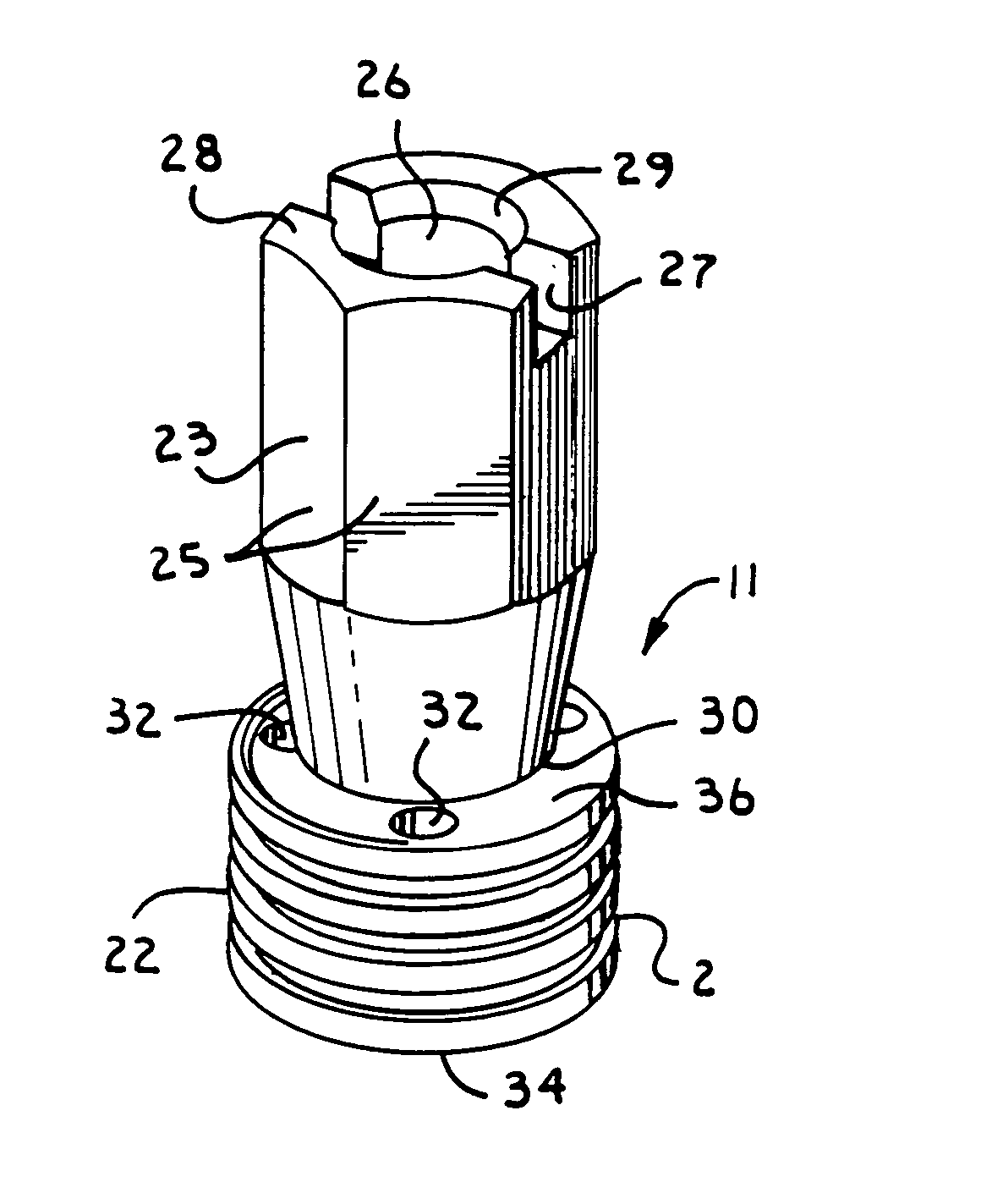
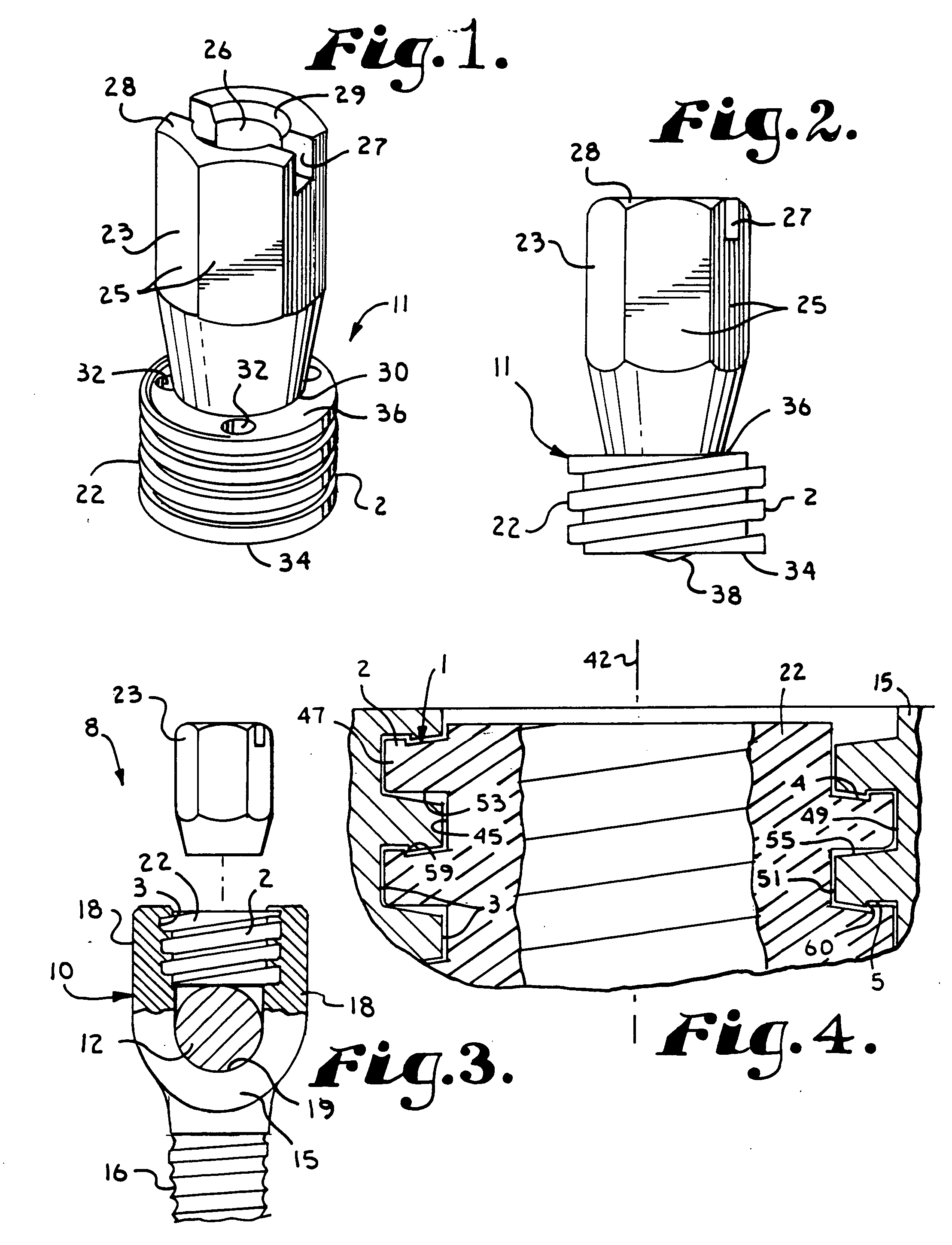
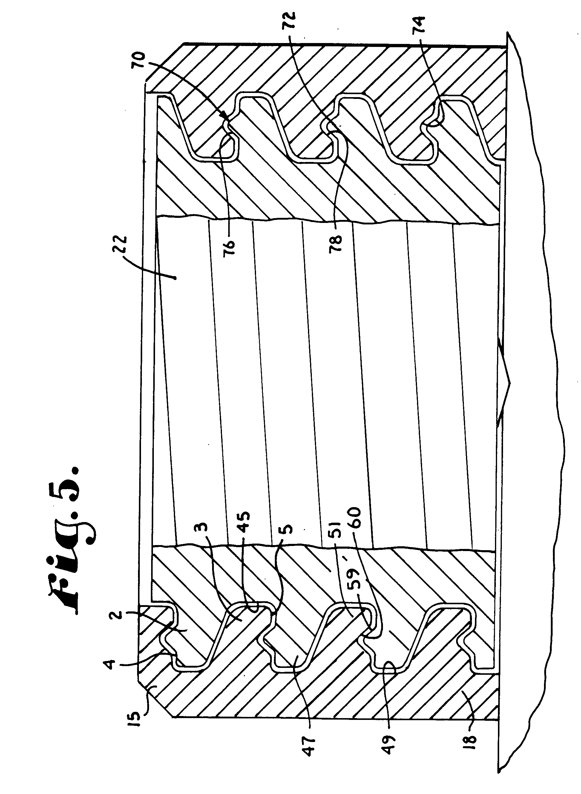
[0057] Referring to the drawings in more detail, the reference numeral 1 generally designates a gripping interlocking form arrangement incorporating a non-linear or compound surface which embodies the present invention. The interlocking form arrangement 1 includes an external interlocking form 2 and internal interlocking form 3 which have respective thrust surfaces 4 and 5 (FIG. 4) and which are used as pairs. The interlocking form arrangement 1 may be used...


PUM


Abstract

A medical implant structure includes a pair of helically wound interlocking forms located on a cylindrical closure for an open headed medical implant and in a receiver between arms of the implant respectively. The interlocking forms each include overlapping gripping elements that engage mating elements during assembly to prevent radial splaying of the arms of the implant. The structure includes dove-tail-like and jig-saw-puzzle-like interlocking forms.

Description

CROSS-REFERENCE TO RELATED APPLICATIONS [0001] This is a continuation-in-part of co-pending U.S. patent application Ser. No. 10 / 831,919 filed Apr. 26, 2004 which is a continuation-in-part of U.S. patent application Ser. No. 10 / 236,123 filed Sep. 6, 2002, now U.S. Pat. No. 6,726,689.BACKGROUND OF THE INVENTION [0002] The present invention is directed to a closure for use between spaced arms of a medical implant for securing a rod to the implant. The structure includes a first interlocking form on a closure and a mating second interlocking form on a receiver. The closure is operably rotated into the receiver. The first and second interlocking forms are both helically wound so that the first interlocking form advances relative to the second interlocking form, when the closure with the first interlocking form is inserted in the receiver and rotated. At least one of the first or second interlocking forms includes a projection that overlaps and radially locks with the other interlocking f...

Claims


Application Information

Patent Timeline
Patent Type & Authority Applications(United States)
IPC IPC(8): A61B17/56A61B17/70A61B17/86F16B33/02F16B35/04
CPCA61B17/7032F16B35/047F16B33/02A61B2017/8655
Inventor JACKSON, ROGER P.
Owner JACKSON
Why Eureka
Try Eureka