AC rotating machine with improved drive for its stator coil

a technology of ac rotating machines and stator coils, which is applied in the direction of motor/generator/converter stoppers, electronic commutators, dynamo-electric converter control, etc., can solve the problems of increasing the total manufacturing cost of the apparatus, complicated structure of the inverter circuit installed in the apparatus for applying the three-phase ac voltage to the synchronous motor, and limited electric power of the device, so as to improve the reliability of the ac rotating machines

Inactive Publication Date: 2009-12-10
DENSO CORP
View PDF7 Cites 62 Cited by
  • Summary
  • Abstract
  • Description
  • Claims
  • Application Information

AI Technical Summary

Benefits of technology

[0026]According to another aspect of the present invention, it is possible to improve the reliability of the AC rotating machine even in the event ...

Problems solved by technology

In addition, if a synchronous motor with a number of phases greater than five were used, toque ripples would be reduced, but the structure of an inverter circuit installed in the apparatus for applying the three-phase AC voltages to the synchronous motor and the structure of the thr...

Method used


Image

  • AC rotating machine with improved drive for its stator coil
  • AC rotating machine with improved drive for its stator coil
  • AC rotating machine with improved drive for its stator coil

Examples


first embodiment

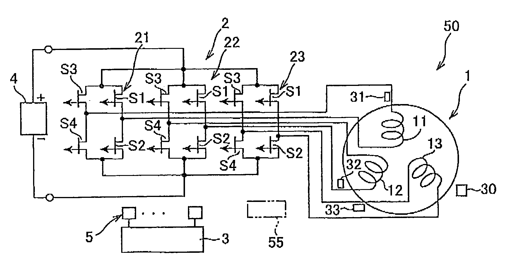
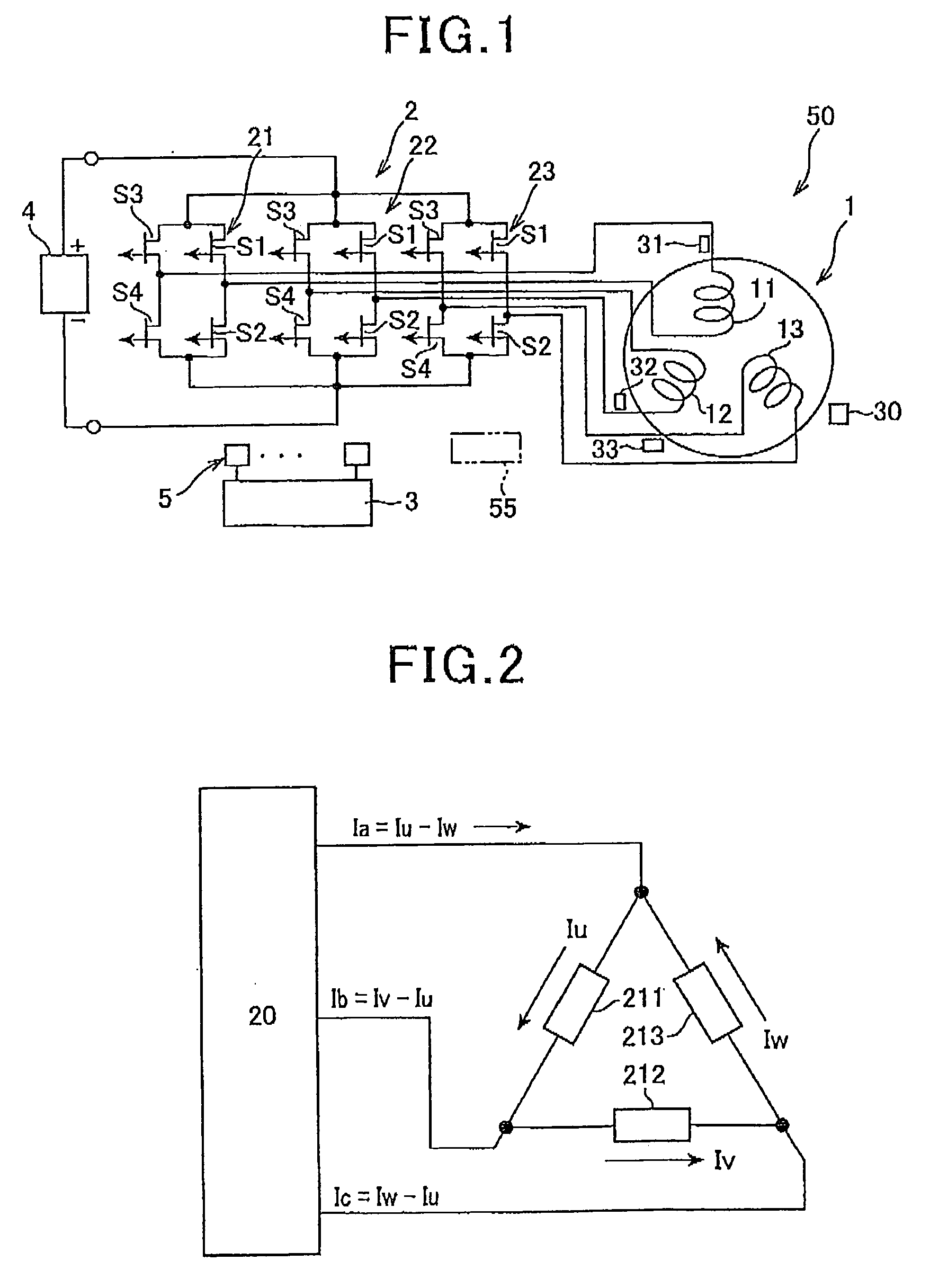
[0036]An example of the structure of an AC motor system 50 according to the first embodiment of the present invention is illustrated in FIG. 1. Referring to FIG. 1, the AC motor system 50 includes a three-phase synchronous motor 1, an inverter circuit 2, a motor controller 3, a direct current (DC) power source 4, and a plurality of drivers 5.

[0037]The three-phase synchronous motor, referred to simply as “synchronous motor”, 1 is designed to be driven by AC voltages. For example, a synchronous reluctance motor or a permanent magnet synchronous motor can be used as the three-phase synchronous motor 1.

[0038]When the synchronous motor 1 is installed in a hybrid vehicle, it is directly or indirectly coupled to a crankshaft of an engine installed in the hybrid vehicle, and serves as a power source together with the engine. When the synchronous motor 1 is installed in an electric vehicle, it serves as a power source of the electric vehicle.

[0039]When the synchronous motor 1 is a three-phas...

second embodiment

[0157]An AC motor system 50A according to the second embodiment of the present invention will be described hereinafter with reference to FIG. 6.

[0158]The structure of the AC motor system 50A according to the second embodiment is substantially identical to that of the AC motor system 50 according to the first embodiment except for the following different points. So, like parts between the AC motor systems 50 and 50A according to the first and second embodiments, to which like reference characters are assigned, are omitted or simplified in description.

[0159]In addition to the components of the AC motor system 50, the AC motor system 50A includes a star-connected stator coil 110, a three-phase inverter 200, a motor controller 300, a DC power source 400, and a plurality of drivers 500.

[0160]The star-connected stator coil 110 consists of a U-phase winding 111, a V-phase stator winding 112, and a W-phase stator winding 113. The three-phase windings 111, 112, and 113 are wound in the slots...


PUM


Abstract

In an AC rotating machine, a stator is provided with N-phase stator windings and located relative to the rotor. The N is an integer equal to or greater than 3, and the N-phase stator windings are arranged to be electrically isolated from each other. An inverter circuit is provided with first to N-th full-bridge inverters. Each of the first to N-th full-bridge inverters includes a first pair of series-connected switching elements and a second pair of series-connected switching elements. The first pair of series-connected switching elements and the second pair of series-connected switching elements are connected in parallel to each other. Each of the first to N-th full-bridge inverters is configured to individually apply a single-phase AC voltage to a corresponding one of the N-phase stator windings to thereby create a torque that rotates the rotor.

Description

CROSS REFERENCE TO RELATED APPLICATIONS[0001]This application is based on Japanese Patent Application 2008-151721 filed on Jun. 10, 2008. This application claims the benefit of priority from the Japanese Patent Application, so that the descriptions of which are all incorporated herein by reference.FIELD OF THE INVENTION[0002]The present invention relates to AC (Alternating Current) rotating machines having a stator coil and a rotor in relation thereto and designed to energize the stator coil to rotate the rotor.BACKGROUND OF THE INVENTION[0003]As examples of various types of AC rotating machines, synchronous motors have been used for wide industrial fields as high-efficiency motors. This is because they have advantages of: eliminating a complicated commutation mechanism with difficult maintenance relative to DC (Direct Current) motors; and reducing secondary copper loss of the rotor as compared with induction motors.[0004]These synchronous motors include permanent magnet synchronous...

Claims


Application Information

Patent Timeline
IPC IPC(8): H02P6/14H02K3/28H02H7/08H02P25/08H02M7/5387H02P27/06H02P27/08H02P29/00
CPCH02P29/022H02P29/032
Inventor OSADA, MASAHIKOMORIMOTO, SHIGEYUKI
Owner DENSO CORP
Why Eureka
Try Eureka