Pressure body arrangement for a claw coupling

a technology of pressure body and claw coupling, which is applied in the direction of yielding coupling, interengaging clutches, and clutches, etc., can solve the problems of restricting construction, significant and undesired deformation of the ring element of the pressure body ring, and uneven pressure distribution, etc., to achieve simple construction, high torque, and the effect of simple construction

Active Publication Date: 2016-11-03
FLENDER GMBH
View PDF7 Cites 1 Cited by
  • Summary
  • Abstract
  • Description
  • Claims
  • Application Information

AI Technical Summary

Benefits of technology

[0009]Due to the presence to such a strengthening ring, a deformation of the ring element in the radial inwards direction is effectively counteracted, so that claw couplings equipped with a pressure body arrangement according to the invention is able to transmit high torques without causing premature wear of the pressure body arrangement. in addition, a pressure body arrangement according to the invention is still simple in construction and can be manufactured and assembled without problems, despite the provision of an additional strengthening ring. The strengthening ring can also be quickly and easily removed and replaced, if need be.
[0010]According to another advantageous feature of the present invention,

Problems solved by technology

This leads to each pressure body of the pressure body ring being pressed together more on the outside than on the inside, which results in an uneven pressure distribution, in which a higher edge pressure acts radially outwards.
Accordingly the pressure bodies are pushed radially inwards during the operation of the claw coupling, thereby frequently causing a significan

Method used


Image

  • Pressure body arrangement for a claw coupling
  • Pressure body arrangement for a claw coupling
  • Pressure body arrangement for a claw coupling

Examples


Embodiment Construction

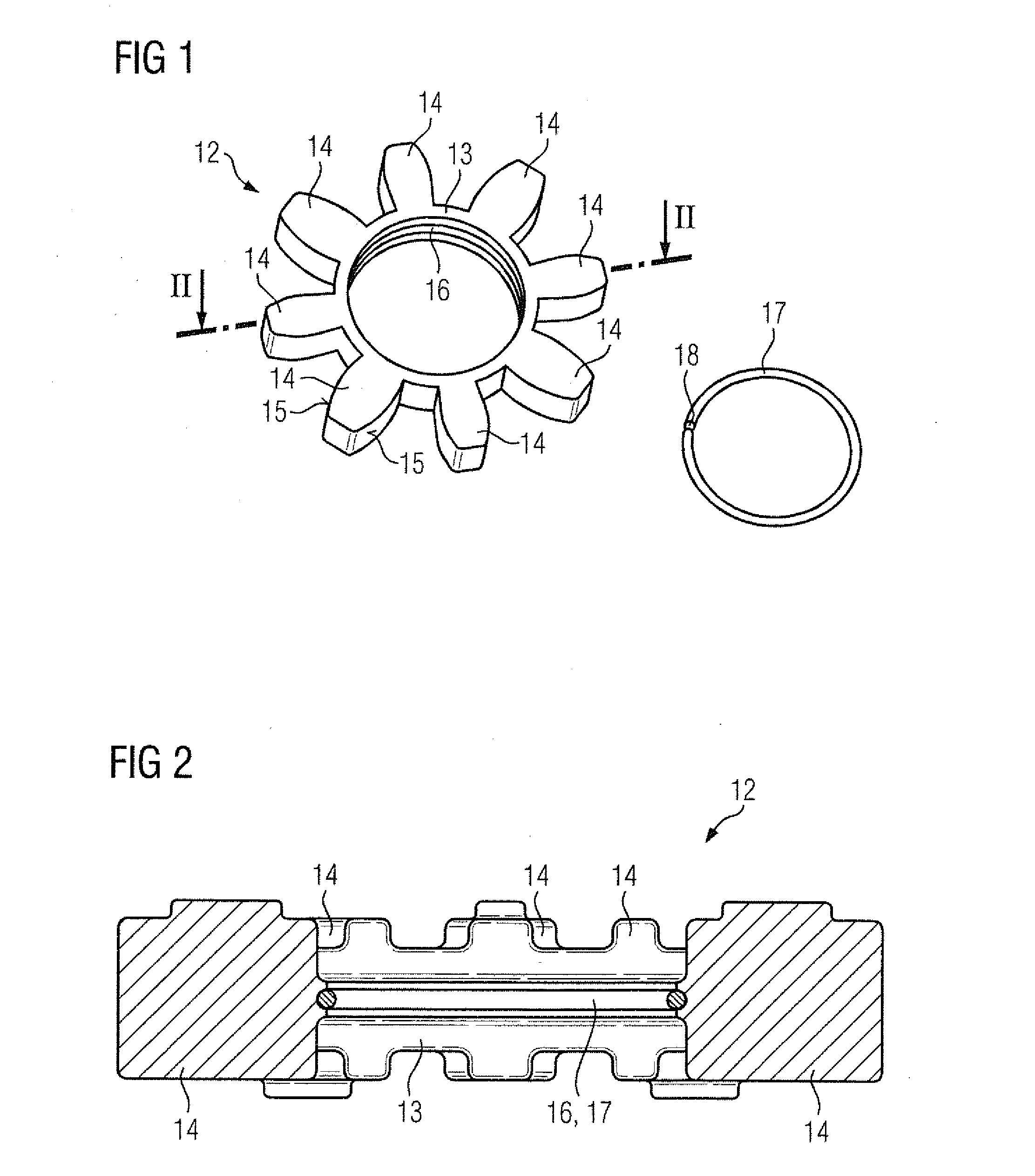
[0019]Throughout all the figures, same or corresponding elements may generally be indicated by same reference numerals. These depicted embodiments are to be understood as illustrative of the invention and not as limiting in any way. It should also be understood that the figures are not necessarily to scale and that the embodiments may be illustrated by graphic symbols, phantom lines, diagrammatic representations and fragmentary views. In certain instances, details which are not necessary for an understanding of the present invention or which render other details difficult to perceive may have been omitted.

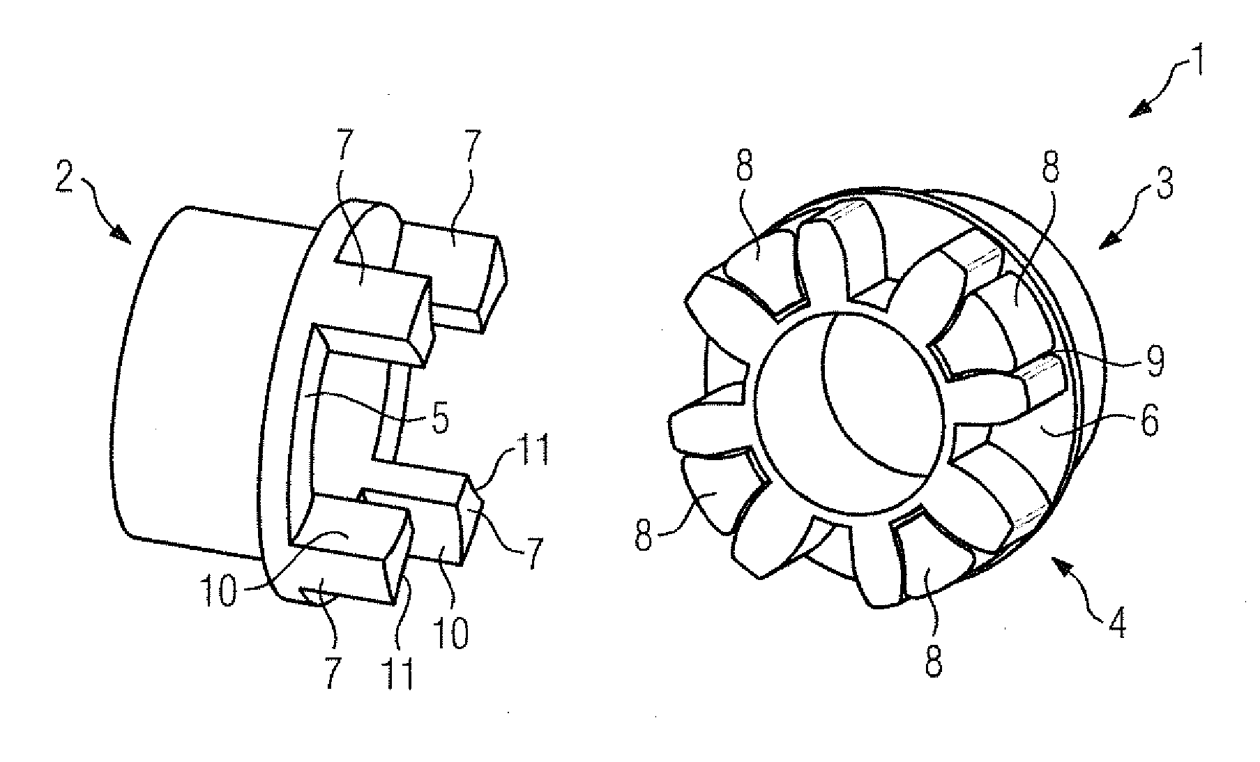
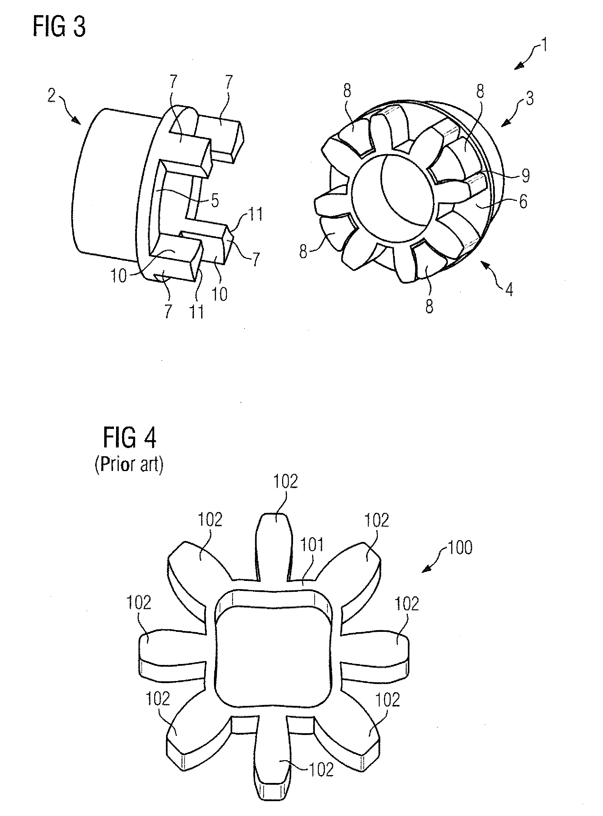
[0020]Turning now to the drawing, and in particular to FIG. 3, there is shown a perspective view of a claw coupling, generally designated by reference numeral 1. The claw coupling 1 serves to transmit torque between two shafts aligned with one another and includes, when assembled, as main components two coupling elements 2, 3 disposed axially opposite one another with aligning long...


PUM


Abstract

A pressure body arrangement for a claw coupling includes a pressure body ring made of elastic material. The pressure body ring includes a ring element and pressure bodies which project radially outwards from the ring element. The ring element has an inner circumference which is provided with a circumferential slot-shaped cutout. Inserted in the slot-shaped cutout such as to be releasable non-destructively is a strengthening ring which is made from a material having a strength which is greater that a strength of the elastic material of the pressure body ring.

Description

CROSS-REFERENCES TO RELATED APPLICATIONS[0001]This application claims the priority of European Patent Application, Serial No. 15165949.7, filed Apr. 30, 2015, pursuant to 35 U.S.C. 119(a)-(d), the disclosure of which is incorporated herein by reference in its entirety as if fully set forth herein.BACKGROUND OF THE INVENTION[0002]The present invention relates to a pressure body arrangement for a claw coupling.[0003]The following discussion of related art is provided to assist the reader in understanding the advantages of the invention, and is not to be construed as an admission that this related art is prior art to this invention.[0004]Claw couplings find application to transmit a torque between two shafts aligning with one another, such as between a motor shaft and a transmission shaft for example, and include two coupling elements disposed axially opposite one another, having end face surfaces facing towards one another, from which claws engaging alternately into one another projec...

Claims


Application Information

Patent Timeline
IPC IPC(8): F16D3/50
CPCF16D3/50F16D11/14F16D3/68
Inventor KLEINEWEGEN, STEFAN
Owner FLENDER GMBH
Why Eureka
Try Eureka