Coaxial gear set

a gear set and coaxial technology, applied in the direction of gears, belts/chains/gearrings, mechanical instruments, etc., can solve the problem of limiting the transmittable torqu

Pending Publication Date: 2022-08-11
KRAKEN INNOVATIONS GMBH
View PDF8 Cites 2 Cited by
  • Summary
  • Abstract
  • Description
  • Claims
  • Application Information

AI Technical Summary

Benefits of technology

[0006]It is therefore the object of the present invention to provide a gear set which avoids the above-mentioned disadvantage. In particular, it should be possible to transmit high torques, preferably with a small overall size. Particularly preferably, a high transmission ratio and a high accuracy or zero backlash are to be achieved.SUMMARY OF THE INVENTION

Problems solved by technology

The line contact has a disadvantageous effect in that it limits the transmittable torques.

Method used


Image

  • Coaxial gear set
  • Coaxial gear set
  • Coaxial gear set

Examples


Embodiment Construction

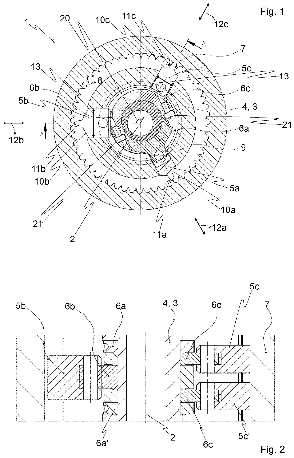
[0063]In FIG. 1, a schematic view of a section normal to an axis of rotation 2 shows a coaxial gear set 1 or crankshaft transmission according to the invention. The coaxial gear set 1 comprises a crankshaft 3 rotatable about the axis of rotation 2 and having at least one connecting rod bearing 4, wherein in the illustrated exemplary embodiment exactly one connecting rod bearing 4 or exactly one crank journal or crank pin is provided.

[0064]Several pistons are connected to the connecting rod bearing 4 in a manner known per se or the pistons are movably mounted on the connecting rod bearing 4, e.g. in each case a divided connecting rod eye of connecting rods 6a, 6b, 6c is fastened to the connecting rod bearing 4 by means of screws 21, cf. FIG. 1, and pistons 5a, 5b, 5c are connected to further connecting rod eyes of the connecting rods 6a, 6b, 6c via piston pins. In the exemplary embodiment of FIG. 1, a total of five pistons are provided, although only the three pistons 5a, 5b, 5c are ...


PUM


Abstract

A coaxial gear set comprising: a crankshaft which can be rotated about an axis of rotation and has at least one connecting rod bearing; and multiple, preferably at least three, pistons, each connected to the crankshaft by means of a connecting rod and which each have a toothing with at least one tooth on a first end face facing away from the axis of rotation. The coaxial gear set also comprises: a hollow shaft having internal toothing, wherein the pistons are located inside the hollow shaft when viewed in a plane normal to the axis of rotation; and a guide unit, wherein the pistons are each linearly guided in the guide unit and can be moved back and forth parallel to a radial direction normal to the axis of rotation, as a result of which the toothings of the first end faces of the pistons can be successively brought into meshing engagement with the internal toothing and out of meshing engagement with said internal toothing.

Description

FIELD OF THE INVENTION[0001]The present invention relates to a coaxial gear set comprising a crankshaft rotatable about an axis of rotation and having at least one connecting rod bearing.DESCRIPTION OF THE PRIOR ART[0002]DE 312164 C describes a self-locking gearbox in which a number of arms arranged in a star shape around a drive shaft are mounted with their inner ends eccentrically on the drive shaft, lie with their central part in guides and engage with their outer ends in a gear rim. In this case, the arms are designed as two-armed levers, the pivots of which are guided in a crosshead-like manner and the inner ends of which rest independently of one another on the driving eccentric, so that the outer ends execute a connecting rod movement and thereby engage successively in the gear rim and drive the latter in the sense opposite to the rotation of the drive shaft. Thus a cycloidal motion results, and from this results a line contact of the outer ends with the teeth of the gear rim...

Claims


Application Information

Patent Timeline
Patent Type & Authority Applications(United States)
IPC IPC(8): F16H25/06F16H49/00
CPCF16H25/06F16H49/001F16H25/2003F16H2025/2037
Inventor EISELE, PHILIPP SIMONMICHELITSCH, MICHAEL
Owner KRAKEN INNOVATIONS GMBH
Why Eureka
Try Eureka