System and method for validating camera calibration in a vision system

a technology of vision system and camera, applied in the field of vision system calibration, can solve the problems of affecting and difficult to trace the root cause of application deterioration performance, so as to reduce recalibration time and overhead, and validate the accuracy of camera calibration. the effect of fast and straightforward system and method

Active Publication Date: 2017-08-15
COGNEX CORP
View PDF61 Cites 61 Cited by
  • Summary
  • Abstract
  • Description
  • Claims
  • Application Information

AI Technical Summary

Benefits of technology

[0007]This invention overcomes disadvantages of the prior art by providing a relatively fast and straightforward system and method in which to validate the accuracy of camera calibration in a single or multiple camera embodiment, utilizing either 2D cameras or 3D imaging sensors. This system and method allows the runtime user to validate camera calibration at any convenient time by imaging a calibration object within the volume space of the camera arrangement. The resulting validation indicates if recalibration is required and can indicate which camera(s) requires recalibration. In an illustrative embodiment the system and method employs an initial calibration process that generates and stores intrinsic parameters and calibration result statistics (including calibration discrepancies between extracted and expected feature positions) based upon images of a first calibration object having a known pattern and dimensions acquired for at least one position within the volume space. A subsequent validation process (a) acquires images of the first calibration object or a second calibration object having a known pattern and dimensions; (b) extracts features of the images of the first calibration object or the second calibration object; (c) predicts positions expected o

Problems solved by technology

Unfortunately, when the vision system operates in adverse environment, such as a manufacturing line, the actual camera position and lens distortions may change due to thermal expansion, vibration, inadvertent foc

Method used


Image

  • System and method for validating camera calibration in a vision system
  • System and method for validating camera calibration in a vision system
  • System and method for validating camera calibration in a vision system

Examples


Embodiment Construction

[0022]A. System Overview and Calibration

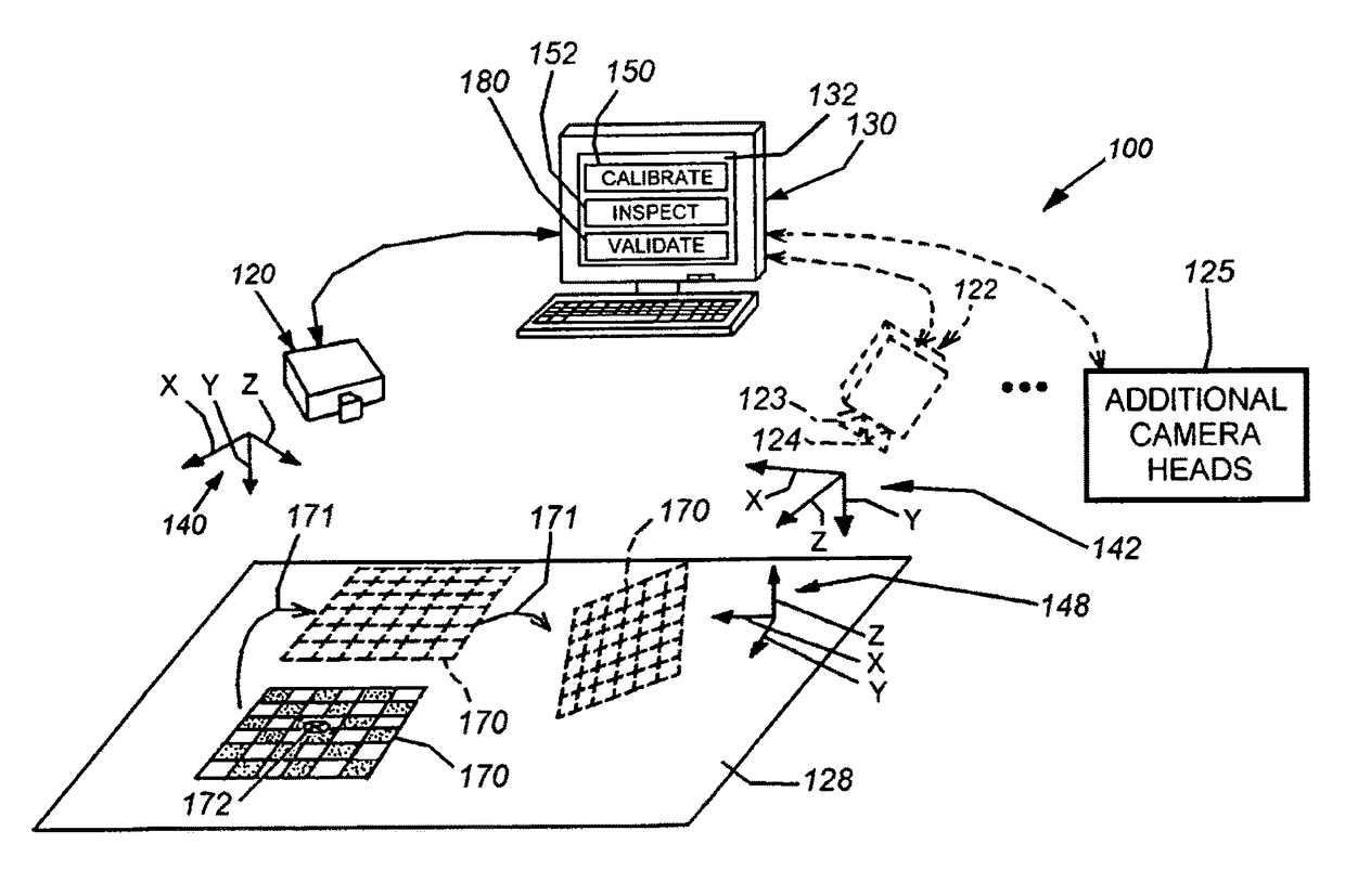
[0023]FIG. 1 depicts a typical arrangement for a vision system 100 for determining the two-dimensional (2D) or three-dimensional (3D) alignment, or pose, of a viewed scene that can include one or more runtime objects to be inspected, aligned, acted upon by a robot manipulator, or any other operation that is controlled or assisted by machine vision processes. The system can be calibrated and validated according to an illustrative embodiment of this invention.

[0024]In general, the system 100 can be any vision system arrangement containing at least one camera having the object-containing scene 128 within its field of view. The camera or sensor can comprise a 2D camera 120 as shown, or optionally, a 3D camera 122 (shown in dashed-line phantom). The 3D camera in this example is a stereo camera head that generates depth images of a scene using optical triangulation between two discrete cameras 123, 124 within a stereo camera head (122), separated by...


PUM


Abstract

This invention provides a system and method to validate the accuracy of camera calibration in a single or multiple-camera embodiment, utilizing either 2D cameras or 3D imaging sensors. It relies upon an initial calibration process that generates and stores camera calibration parameters and residual statistics based upon images of a first calibration object. A subsequent validation process (a) acquires images of the first calibration object or a second calibration object having a known pattern and dimensions; (b) extracts features of the images of the first calibration object or the second calibration object; (c) predicts positions expected of features of the first calibration object or the second calibration object using the camera calibration parameters; and (d) computes a set of discrepancies between positions of the extracted features and the predicted positions of the features. The validation process then uses the computed set of discrepancies in a decision process that determines whether at least one of the discrepancies exceeds a predetermined threshold value. If so, recalibration is required. Where multiple cameras are employed, extrinsic parameters are determined and used in conjunction with the intrinsics.

Description

FIELD OF THE INVENTION[0001]This invention relates to vision systems and more particularly to calibration of vision system cameras.BACKGROUND OF THE INVENTION[0002]Machine vision systems are commonly employed in industry to determine the alignment of parts and objects with respect to a predetermined two-dimensional (2D) or three-dimensional (3D) coordinate space. These systems employ various techniques and programs to determine alignment of objects, often based on trained models of the objects. Camera calibration is an essential step in computer vision—both in two-dimensional (2D) and three-dimensional (3D) imaging systems. Camera calibration involves modeling a camera's position and lens characteristics usually by estimating the intrinsic and extrinsic parameters. Camera calibration can be performed on either a single camera or a multi-camera arrangement, such as a system that includes one or more stereo camera heads. Stereo camera heads, and other forms of 3D sensors, enable the g...

Claims


Application Information

Patent Timeline
IPC IPC(8): G06K9/20
CPCG06K9/209G06T7/85G06T7/00
Inventor YE, XIANGYUNWALLACK, AARON S.SHIVARAM, GURUPRASADMARRION, CYRIL C.LI, DAVID Y.
Owner COGNEX CORP
Why Eureka
Try Eureka