
Camera Lens Calibration System

a technology of lens calibration and lens lens, applied in the field of camera lens calibration system, can solve the problems of optical system not being focused, the quality of ambient modular transfer function (mtf) cannot be guaranteed when focusing, and the object point will not be ideal, etc., and achieves the effects of long focus time, high labor cost, and high production cos

Active Publication Date: 2012-07-05
ALTEK (KUNSHAN) CO LTD
View PDF8 Cites 31 Cited by
  • Summary
  • Abstract
  • Description
  • Claims
  • Application Information

AI Technical Summary

Benefits of technology

[0015]A primary object of the present invention is to provide a camera lens calibration system to solve the problems of long focus time of conventional camera lens calibration machine, high labor cost or high production cost.

Problems solved by technology

Thus, due to spherical surface effect of the lens, object point will not be an ideal object point when shooting.
The disadvantage is that the quality of ambient modular transfer function (MTF) cannot be ensured when focusing.
In addition, some of the optical system cannot be focused because the diffraction core image is not sensitive to the relative lens movement.2. Using CMOS module and image processing component to analyze pattern and perform comparison by bar transmission mechanism.
The disadvantage is the high expense of the CMOS module, computer and bar transmission module for processing image and auto focus function.
In addition, the automatic focusing takes a long time.
Moreover, it needs manual operation to adjust camera lens after computer data detection.
The disadvantage is that the manual operation will require the operator to see the data showing on the computer screen and to adjust the required relative moving distance of X / Y axis of the camera lens platform.
It further requires large labor cost and the focus time is too long.
The present methods or devices of focus have the problems of long focus time, high labor cost or high reducing cost.

Method used


Image

  • Camera Lens Calibration System
  • Camera Lens Calibration System
  • Camera Lens Calibration System

Examples


Embodiment Construction

[0026]The present invention will now be described with some preferred embodiments thereof and with reference to the accompanying drawings. For the purpose of being easy to understand, elements that are the same in the preferred embodiments are denoted by the same reference numerals. Drawings in the detailed description are to express meaning and assist description, which are not necessary the true proportion and accurate displacement as the embodiment of the present invention. Thus the claim of the embodiment of the present invention is not limited to the proportion and displacement relationship of the attached drawings.

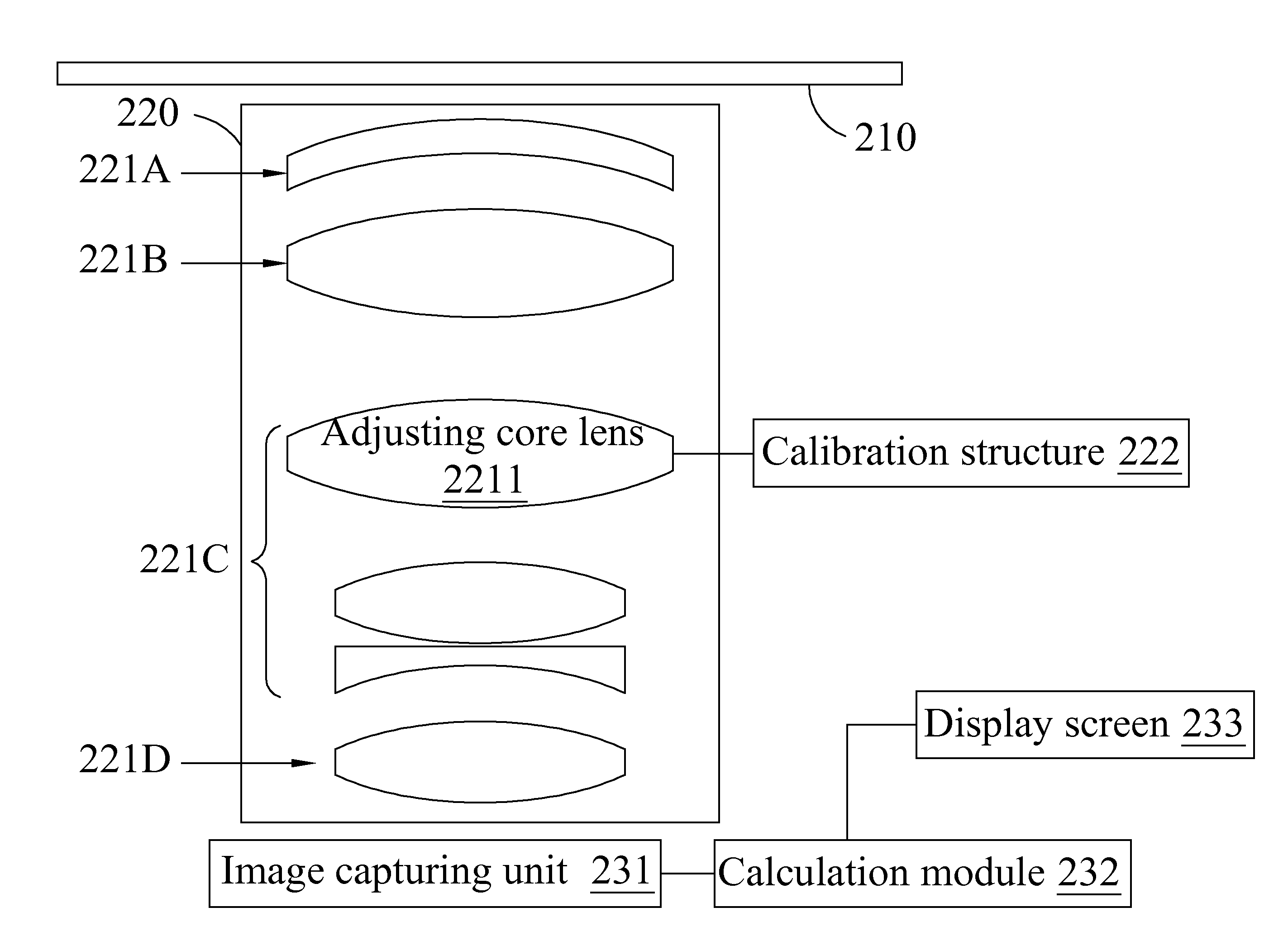
[0027]Please refer to FIG. 2 and FIG. 3. FIG. 2 is a block diagram of a camera lens calibration system according to an embodiment of the present invention. FIG. 3 is a schematic diagram of a camera lens calibration system according to an embodiment of the present invention. In FIG. 2, a camera lens calibration system 200 comprises a display module 210, a calibration ...


PUM


Abstract

The invention is discloses a camera lens calibration system and method thereof, which comprise a calibration platform, the calibration platform comprise a calibration structure. A calibration camera lens to be calibrated is placed on the calibration platform. An image testing module is provided for capturing a target pattern from a target pattern display through the calibration camera lens to be calibrated for getting an image pattern. The image testing module provides a contrast parameter computation for calculating the contrast parameter of image pattern and showing results on a display.

Description

FIELD OF THE INVENTION[0001]The exemplary embodiment(s) of the present invention relates to a camera lens calibration system and a method thereof. More specifically, the exemplary embodiment(s) of the present invention relates to a camera lens calibration system and a method thereof which enables the result comparison of the captured contrast values of the image patterns to help calibrate the focus on the camera lens.BACKGROUND OF THE INVENTION[0002]Ideal camera lens should have the following conditions when imaging:[0003]a. Dots should be imaged as dots.[0004]b. Faces right ahead should be imaged perpendicular to optical axis as the right faces.[0005]c. Object to be shot should be similar to image producing from lens.[0006]d. Colors of image should be presented true.[0007]Theoretically, neglecting areas outside the optical axis of the imaging face can produce a standard image. However, regular picture taking uses large aperture to have enough light. Focus is not limited to near opt...

Claims


Application Information

Patent Timeline
Patent Type & Authority Applications(United States)
IPC IPC(8): H04N17/00G03B13/18G03B13/20
CPCG03B2205/0092G03B43/00G03B2205/00
Inventor WANG, PENG-KUNZHANG, BINSHEN, MING
Owner ALTEK (KUNSHAN) CO LTD
Learn More