Method and apparatus for camera calibration, and vehicle

A technology of a calibration device and a camera, which is applied in the field of vehicles and can solve the problems of time-consuming calibration of the environment and the like

Inactive Publication Date: 2008-08-06
SANYO ELECTRIC CO LTD
View PDF2 Cites 33 Cited by
  • Summary
  • Abstract
  • Description
  • Claims
  • Application Information

AI Technical Summary

Problems solved by technology

However, in this method, it is also necessary to set a coordinate (two-dimensional global coordinate) system shared between a plurality of images, so it cannot solve the problem of time-consuming setup of the calibration environment.

Method used


Image

  • Method and apparatus for camera calibration, and vehicle
  • Method and apparatus for camera calibration, and vehicle
  • Method and apparatus for camera calibration, and vehicle

Examples


no. 1 example 》

[0092] The first embodiment will be described. FIG. 10 is a flowchart showing the procedure of correction processing according to the first embodiment. The correction processing according to the first embodiment is constituted by each processing of steps S11 to S14, step S11 is executed by each camera and the image processing device 10, and steps S12 to S14 are executed by the image processing device 10.

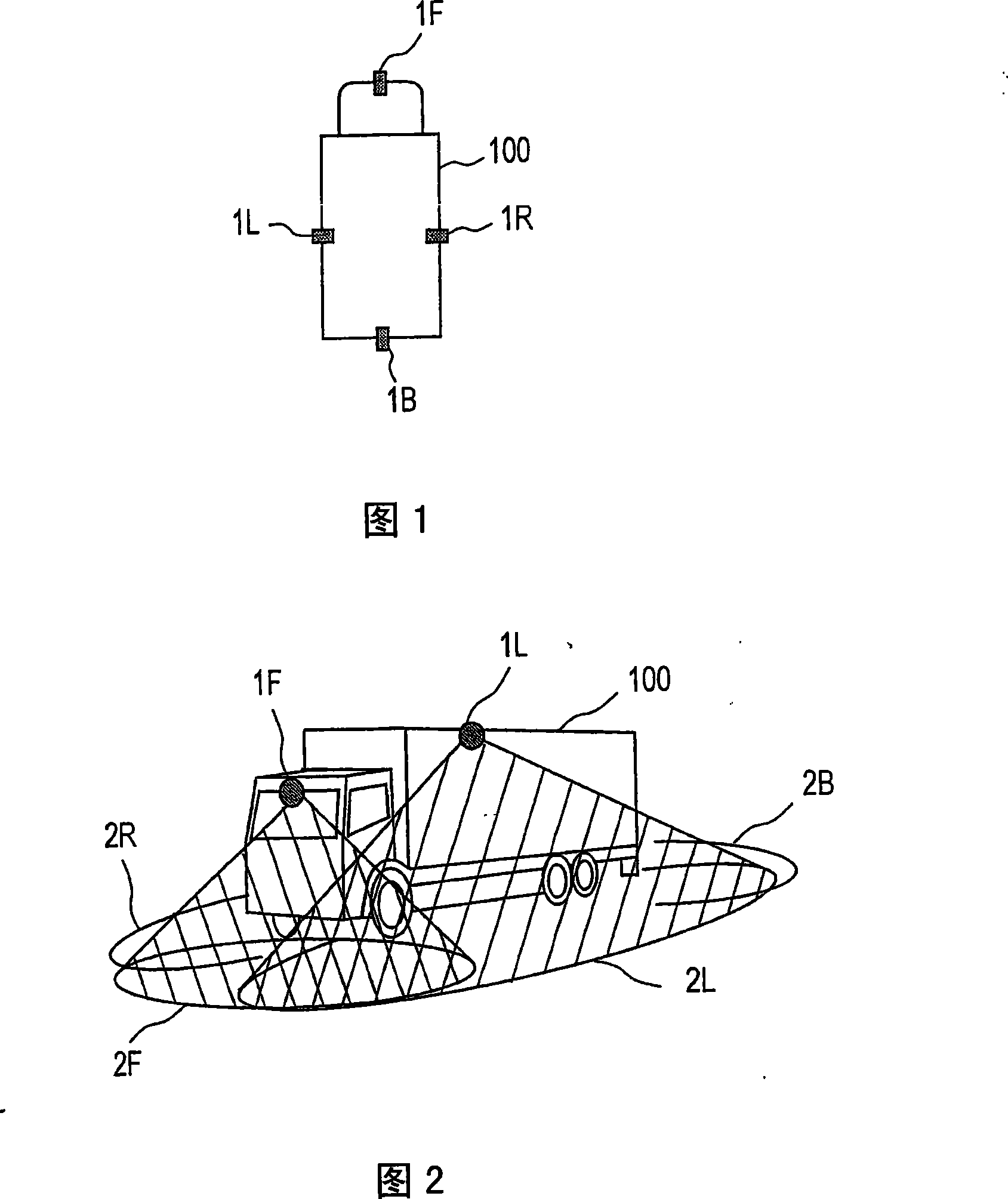
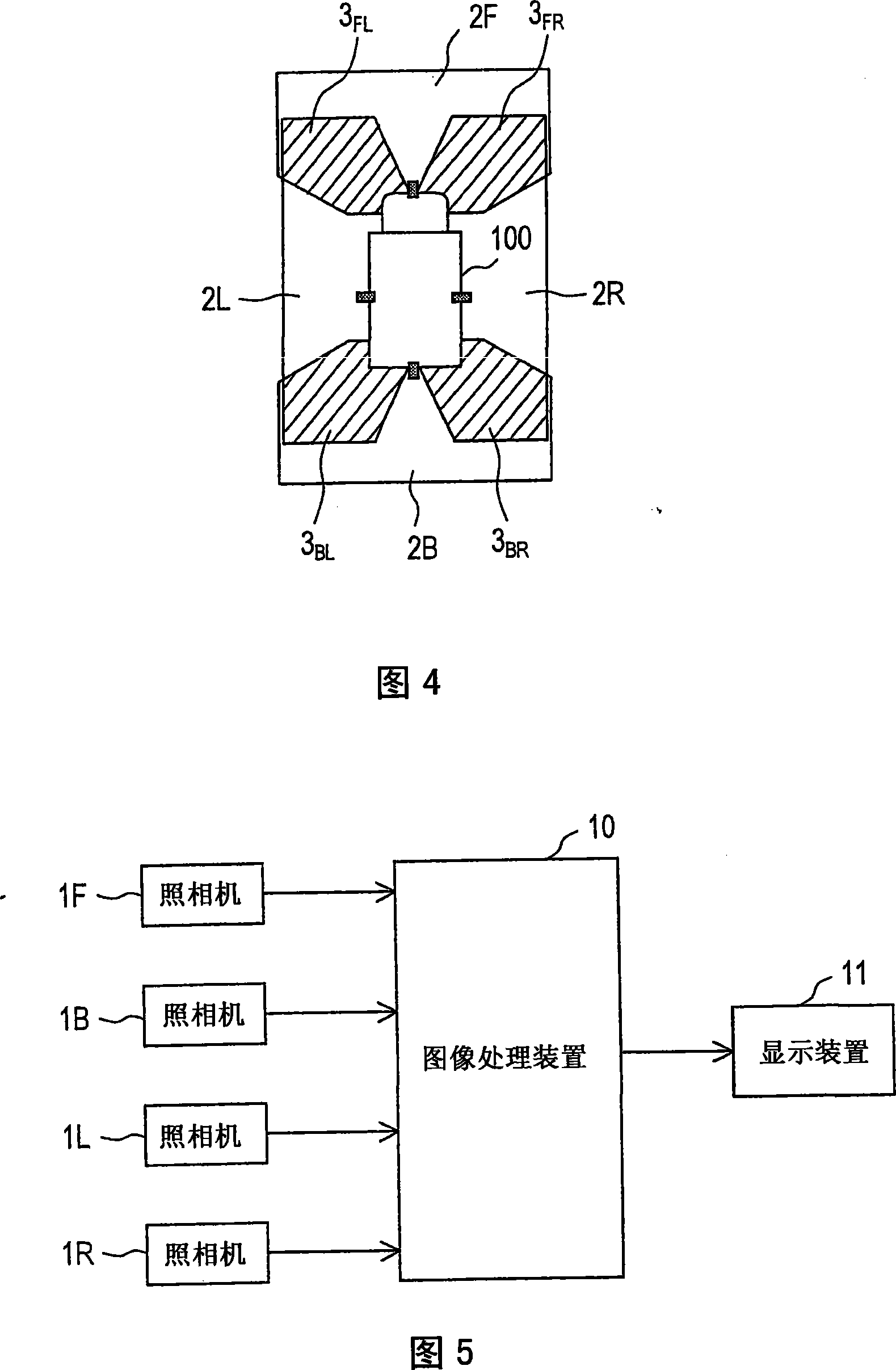
[0093] First, in step S11 , each camera is made to take an image while each calibration pattern is arranged in each common imaged area as described above (see FIG. 6 ), and the image processing device 10 obtains an imaged image from each camera. Hereinafter, the photographed image obtained here will be specifically referred to as a photographed image for calibration. FIG. 11 shows examples of the acquired calibration photographic images. In FIG. 11 , marks 301 , 302 , 303 , and 304 respectively indicate images captured by cameras 1F, 1R, 1L, and 1B for calibration.

[009...

no. 2 example 》

[0122] Next, a second embodiment will be described. FIG. 16 is a flowchart showing the procedure of correction processing according to the second embodiment. The correction processing according to the second embodiment is constituted by each processing of steps S11 to S13 and the processing of step S24. Each processing of steps S11 to S13 is the same as those in the first embodiment (FIG. 10).

[0123] In step S13, each bird's-eye view image obtained in step S12 should be aligned and synthesized through rigid body transformation in such a manner that the coordinates of the corresponding correction patterns are consistent, but as described in the first embodiment (refer to 15, etc.), due to error reasons, usually, the projection points of the feature points on the composite image (full-circumference bird's-eye view image) are not completely consistent between the two cameras. In the first embodiment, the inconsistency of the projection points is reduced by step S14, but in th...

no. 3 example 》

[0138] Next, as an illustration for the homography matrix H 1 ’~H 4 ’, the third embodiment will be described. The third embodiment corresponds to a modified example of the second embodiment. The flowchart showing the procedure of the correction processing according to the third embodiment is the same as the flowchart ( FIG. 16 ) according to the second embodiment, and the correction processing according to the third embodiment is composed of steps S11 to S13 and S24. However, in the third embodiment, the homography matrix H in step S24 1 ’~H 4 The optimization method of ' is different from the second embodiment. Therefore, below, this optimization method, which is a point different from the second embodiment, will be described.

[0139] In the present embodiments including the third example, the shape of the correction pattern is made a square. A square is invariant to rotation with one degree of freedom and parallel movement with two degrees of freedom. Therefore, the...


PUM


Abstract

A camera calibration apparatus has a parameter deriver adapted to find parameters for projecting images shot with N cameras (where N is an integer of 3 or more) onto a predetermined surface and merging the images together. The N cameras comprise a first camera, a second camera, . . . and an N-th camera. The i-th camera (where i is every integer between 1 and N, inclusive) shares a common shooting area with at least one of the other (N-1) cameras, so that there are a plurality of such common shooting areas in total. The parameter deriver finds the parameters based on the results of the shooting of the calibration patterns arranged in the common shooting areas with the corresponding cameras. The calibration patterns are arranged separate from one another.

Description

technical field [0001] The present invention relates to a camera calibration device and a camera calibration method for realizing calibration processing necessary for projecting and synthesizing captured images of a camera onto a predetermined surface, and to a vehicle using the camera calibration device and camera calibration method. Background technique [0002] With the improvement of security awareness in recent years, there are more and more cases where cameras (vehicle cameras) are installed in vehicles such as automobiles. In addition, research is being carried out to not only display camera images, but also use image processing technology to make people view softer images. One of them is to generate and display a bird's-eye view image as viewed from above the ground by performing coordinate transformation on the captured image. By displaying the bird's-eye view image, the driver can easily grasp the situation around the vehicle. [0003] Furthermore, a field of vie...

Claims


Application Information

Patent Timeline
Patent Type & Authority Applications(China)
IPC IPC(8): G06T7/00B60R1/00
CPCG06T7/0018H04N17/002G06T7/80
Inventor 浅利圭介蚊野浩奥田浩三石井洋平
Owner SANYO ELECTRIC CO LTD
Why Eureka
Try Eureka