System and method for runtime determination of camera miscalibration

A calibration error and camera technology, applied in the field of vision systems, can solve the problems of 3D vision system deterioration, the risk of false rejection/false acceptance of camera calibration, etc.

Active Publication Date: 2012-11-14
COGNEX CORP
View PDF9 Cites 31 Cited by
  • Summary
  • Abstract
  • Description
  • Claims
  • Application Information

AI Technical Summary

Problems solved by technology

Conversely, too few inspections may expose the 3D vision system to the risk of excessive false rejections / false acceptances of degraded camera calibration

Method used


Image

  • System and method for runtime determination of camera miscalibration
  • System and method for runtime determination of camera miscalibration
  • System and method for runtime determination of camera miscalibration

Examples


Embodiment Construction

[0021] A. Systematic review and calibration

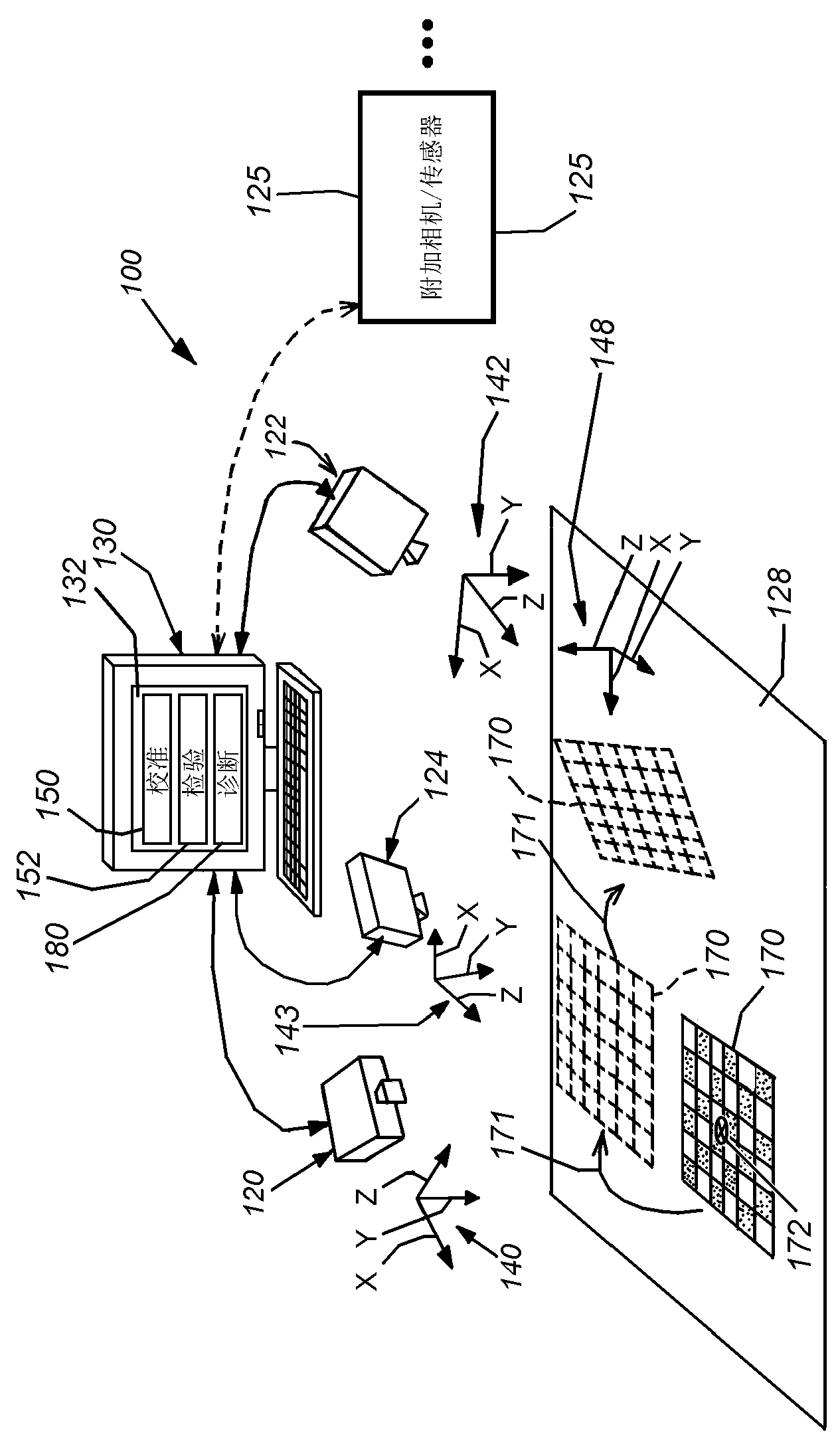
[0022] figure 1 A typical mechanism for a vision system 100 is described to determine the two-dimensional (2D) or three-dimensional (3D) calibration or pose of a viewed scene, which may include one or more A runtime object that controls or assists other operations to inspect, align, and actuate. The system can be calibrated (and the calibration can be followed by self-diagnostics) according to an illustrative embodiment of the present invention.

[0023]In general, system 100 may be any vision system mechanism that includes at least three cameras having a scene 128 containing an object within its field of view. The camera(s) or sensor(s) 120, 122, 124 may each comprise a 2D camera as shown, or alternatively, a 3D sensor. When provided, 3D sensor sensors may be adapted to produce a depth image of a scene using optical triangulation within a stereo camera between two discrete cameras (binocular viewing) separated by a known bas...


PUM


Abstract

This invention provides a system and method for runtime determination (self- diagnosis) of camera miscalibration (accuracy), typically related to camera extrinsics, based on historical statistics of runtime alignment scores for objects acquired in the scene, which are defined based on matching of observed and expected image data of trained object models. This arrangement avoids a need to cease runtime operation of the vision system and / or stop the production line that is served by the vision system to diagnose if the system's camera(s) remain calibrated. Under the assumption that objects or features inspected by the vision system over time are substantially the same, the vision system accumulates statistics of part alignment results and stores intermediate results to be used as indicator of current system accuracy. For multi-camera vision systems, cross validation is illustratively employed to identify individual problematic cameras. The system and method allows for faster, less- expensive and more-straightforward diagnosis of vision system failures related to deteriorating camera calibration.

Description

technical field [0001] The present invention relates to vision systems and more particularly to calibration of vision system cameras. Background technique [0002] Machine vision systems are commonly used in industry to determine the alignment of parts and objects with respect to a preset two-dimensional (2D) or three-dimensional (3D) coordinate space. These systems employ various techniques and procedures, often based on trained models of the object, to determine the alignment of the object. Camera calibration is an important step in computer vision—both in two-dimensional (2D) and three-dimensional (3D) imaging systems. Camera calibration involves the modeling of camera position and lens properties known as extrinsic and intrinsic parameters. Camera calibration can be performed on a single camera or in a multi-camera configuration such as a system including one or more stereo cameras. Stereo cameras and other forms of 3D sensors are capable of producing an image of the ...

Claims


Application Information

Patent Timeline
Patent Type & Authority Applications(China)
IPC IPC(8): G06T7/00
CPCG06T2207/30108G06T7/002G06T2207/10012G06T7/85
Inventor 叶芗芸D·Y·李G·什瓦拉姆D·J·迈克尔
Owner COGNEX CORP
Why Eureka
Try Eureka