

Method for dish reflector illumination via sub-reflector assembly with dielectric radiator portion
a technology of dielectric radiator and reflector, which is applied in the direction of antennas, waveguide mouths, electrical appliances, etc., can solve the problem of increasing the overall manufacturing cos
- Summary
- Abstract
- Description
- Claims
- Application Information
AI Technical Summary
Benefits of technology
Problems solved by technology
Method used
Image

Examples
Embodiment Construction
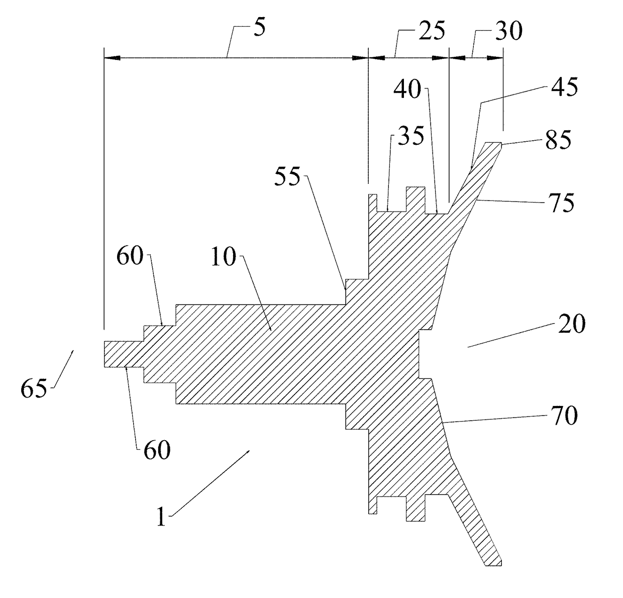
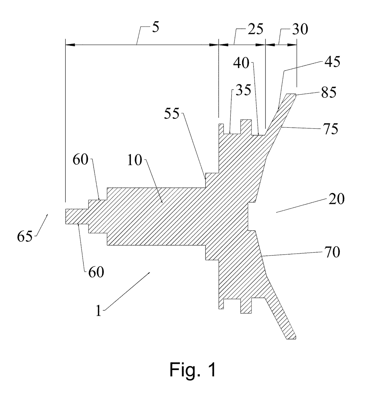
[0022]The inventor has recognized that improvements in radiation pattern control and thus overall reflector antenna performance may be realized by reducing or minimizing the electrical effect of the feed boom end and sub-reflector overspill upon the radiation pattern of conventional dielectric cone sub-reflector assemblies, by providing reflector dish illumination that is spaced away from the vertex area of the reflector dish.
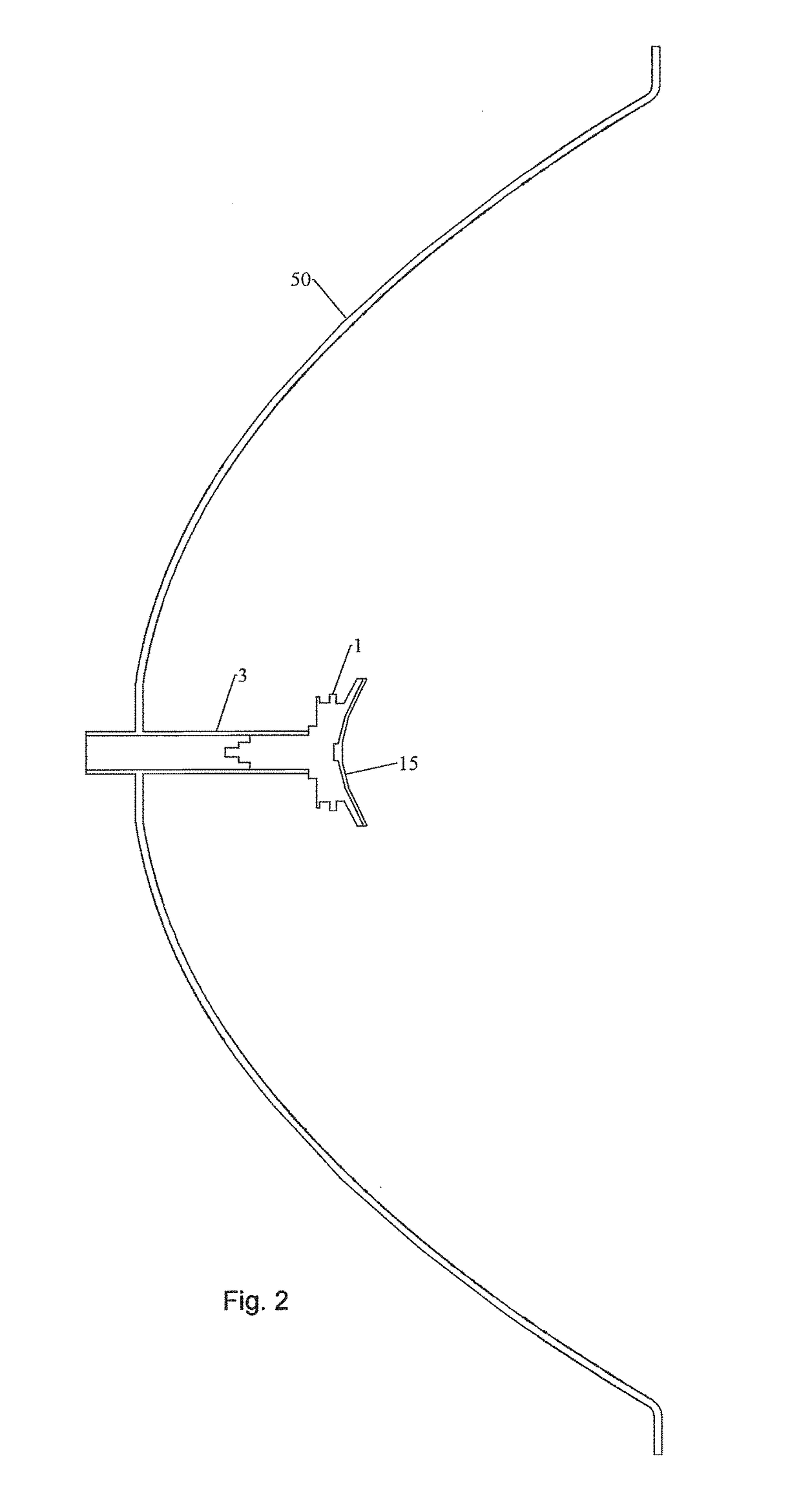
[0023]As shown in FIGS. 1, 2 and 4, a cone radiator sub-reflector assembly 1 is configured to couple with the end of a feed boom waveguide 3 at a waveguide transition portion 5 of a unitary dielectric block 10 which supports a sub-reflector 15 at the distal end 20. The sub-reflector assembly 1 utilizes an enlarged sub-reflector diameter for reduction of sub-reflector spill-over. The sub-reflector 15 may be dimensioned, for example, with a diameter that is 2.5 wavelengths or more of a desired operating frequency, such as the mid-band frequency of a desired micro...
PUM
 Abstract
Description
Claims
Application Information