Controlled illumination dielectric cone radiator for reflector antenna

a dielectric cone radiator and reflector technology, applied in the direction of antennas, waveguide devices, basic electric elements, etc., can solve the problem of increasing the overall manufacturing cos

Active Publication Date: 2016-02-11
COMMSCOPE TECH LLC
View PDF2 Cites 2 Cited by
  • Summary
  • Abstract
  • Description
  • Claims
  • Application Information

AI Technical Summary

Benefits of technology

[0020]The inventor has recognized that improvements in radiation pattern control and thus overall reflector antenna performance may be realized by reducing or minimizing the electrical effect of the feed boom end and sub-reflector overspill upon the radiation pattern of conventional dielectric cone sub-reflector assemblies.
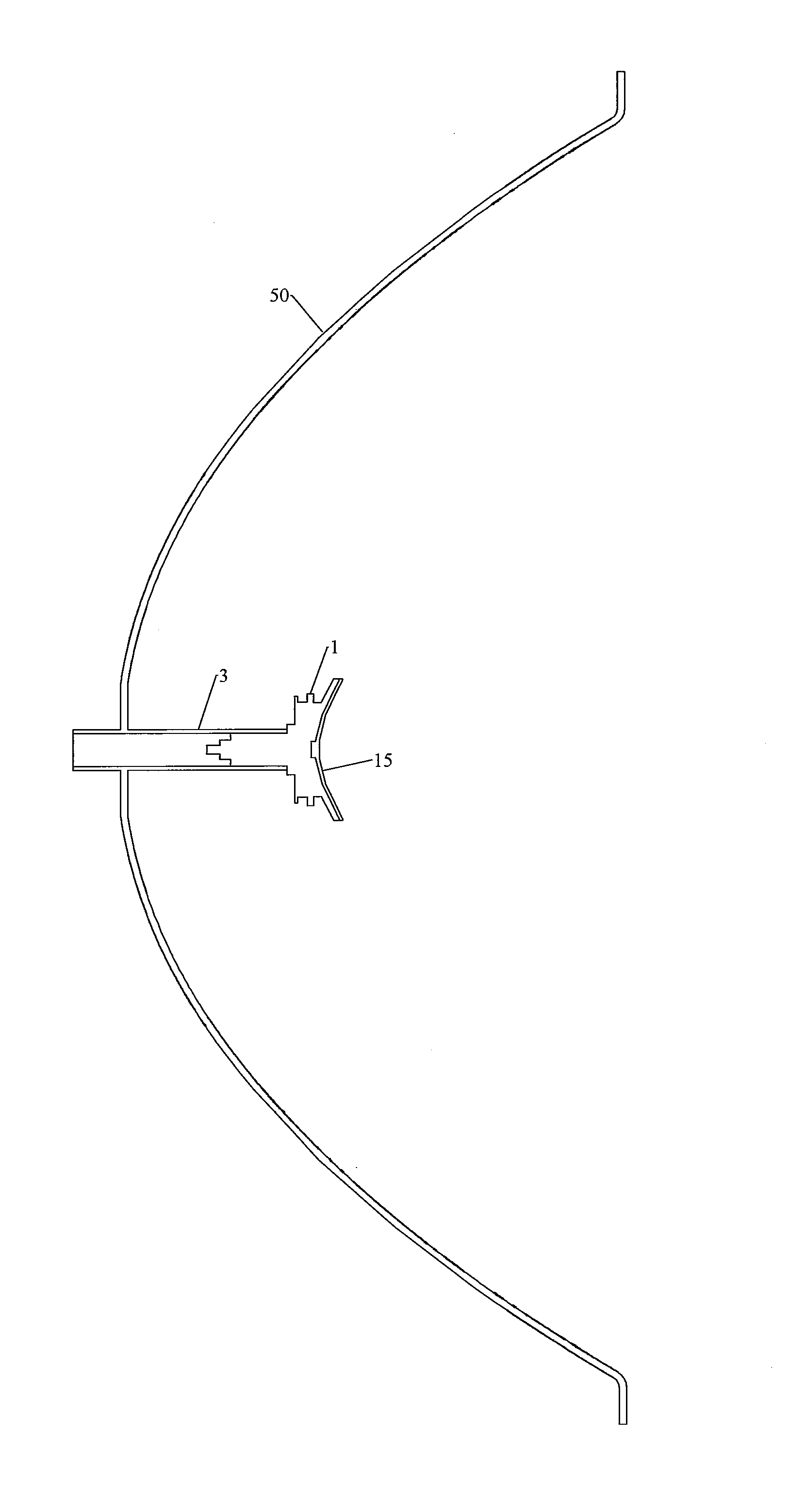
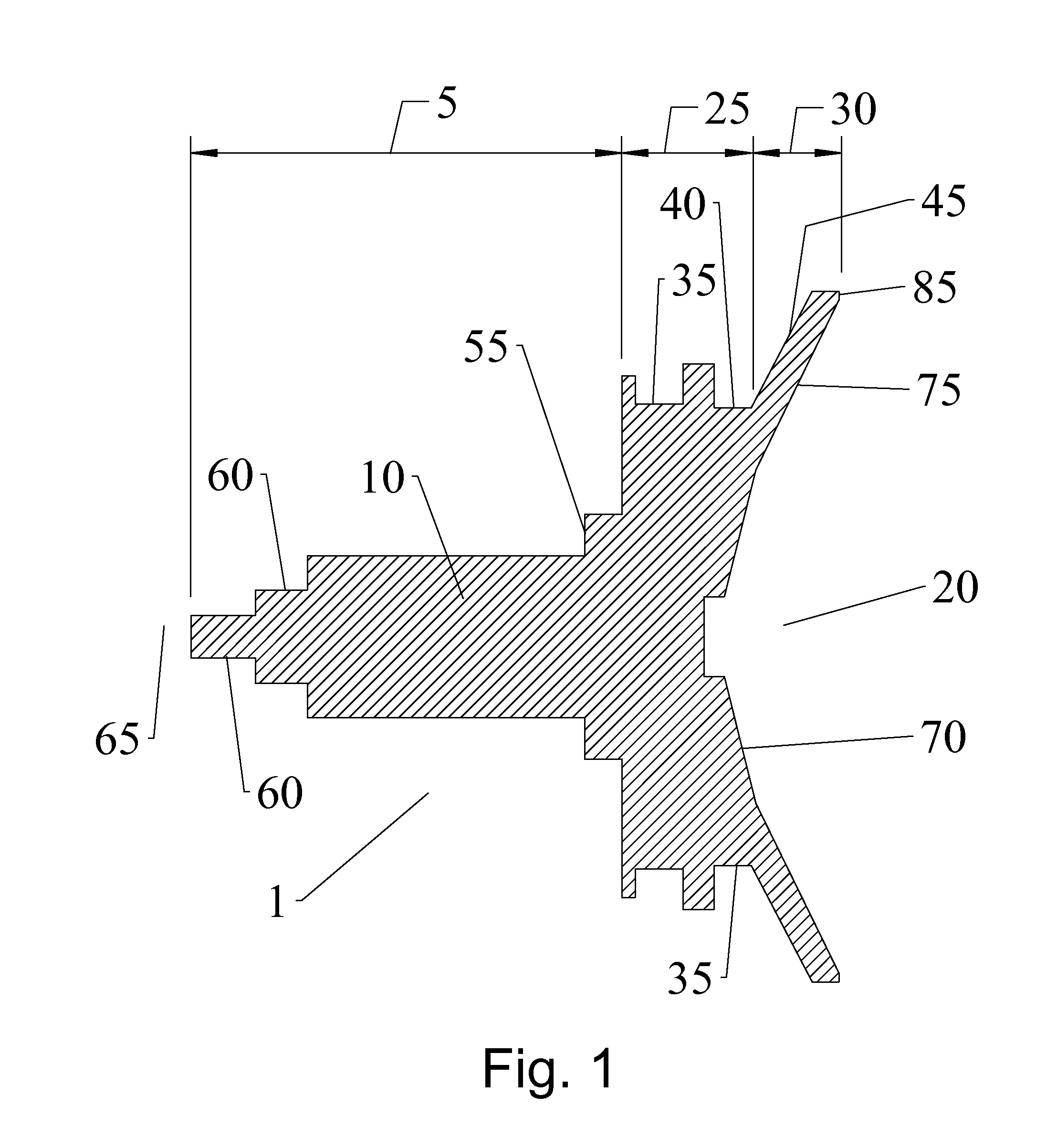
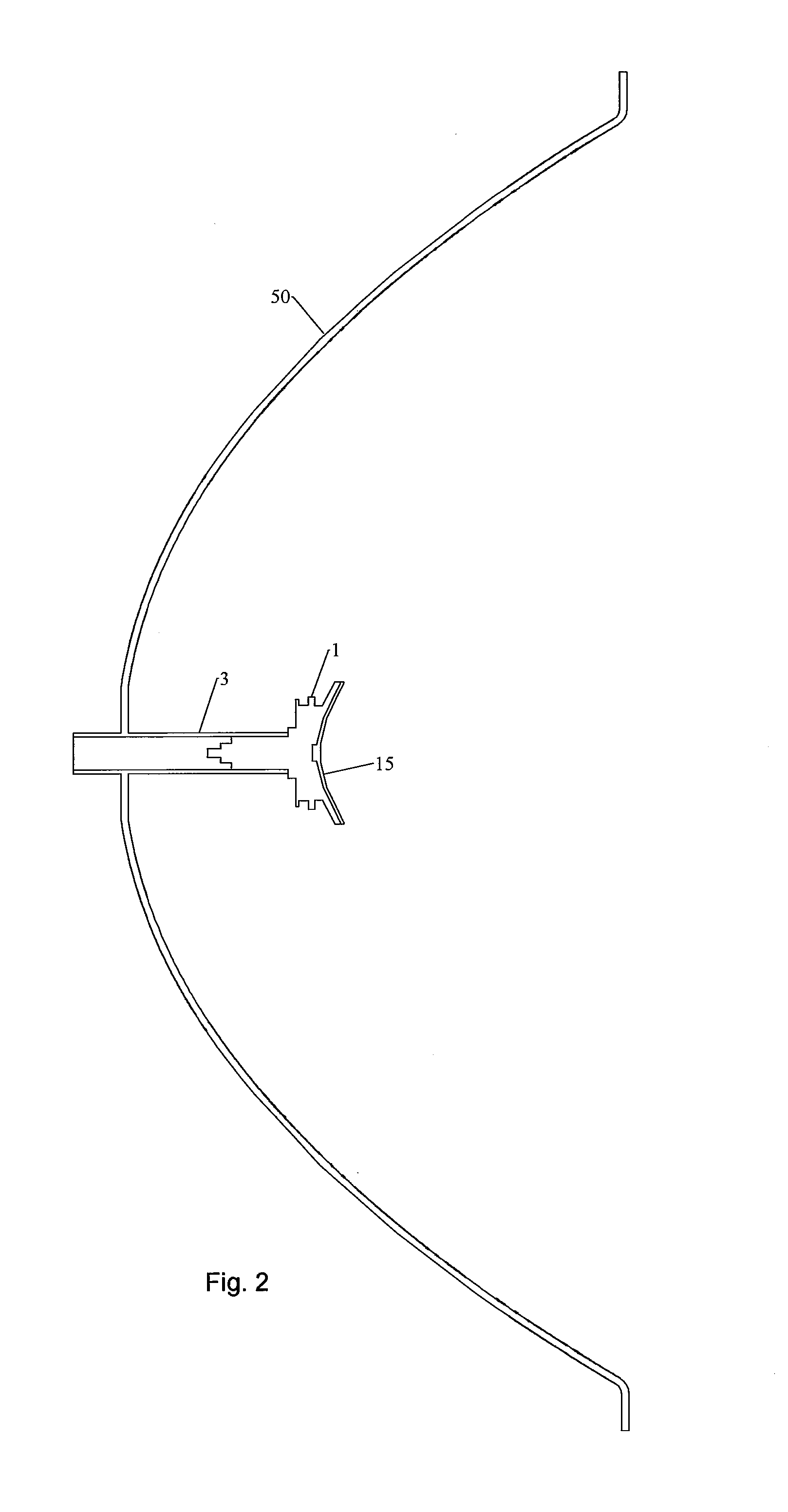
[0034]From the foregoing, it will be apparent that the present invention brings to the art a sub-reflector assembly 1 for a reflector antenna with improved electrical performance and significant manufacturing cost efficiencies. The sub-reflector assembly 1 according to the invention is strong, lightweight and may be repeatedly cost efficiently manufactured with a very high level of precision.Table of Parts1sub-reflector assembly3waveguide5waveguide transition portion10dielectric block15sub-reflector20distal end25dielectric radiator portion30sub-reflector support portion35groove40distal groove45distal sidewall50dish reflector55shoulder60step65proximal end70proximal conical surface75distal conical surface80disk85reference surface90shield95RF absorbing material

Problems solved by technology

Further, the plurality of angled features and / or steps in the dielectric block requires complex manufacturing procedures which increase the overall manufacturing cost.

Method used


Image

  • Controlled illumination dielectric cone radiator for reflector antenna
  • Controlled illumination dielectric cone radiator for reflector antenna
  • Controlled illumination dielectric cone radiator for reflector antenna

Examples


Embodiment Construction

[0020]The inventor has recognized that improvements in radiation pattern control and thus overall reflector antenna performance may be realized by reducing or minimizing the electrical effect of the feed boom end and sub-reflector overspill upon the radiation pattern of conventional dielectric cone sub-reflector assemblies.

[0021]As shown in FIGS. 1, 2 and 4, a cone radiator sub-reflector assembly 1 is configured to couple with the end of a feed boom waveguide 3 at a waveguide transition portion 5 of a unitary dielectric block 10 which supports a sub-reflector 15 at the distal end 20. The sub-reflector assembly 1 utilizes an enlarged sub-reflector diameter for reduction of sub-reflector spill-over. The sub-reflector 15 may be dimensioned, for example, with a diameter that is 2.5 wavelengths or more of a desired operating frequency, such as the mid-band frequency of a desired microwave frequency band. The exemplary embodiment is dimensioned with a 39.34 mm outer diameter and a minimum...


PUM


Abstract

A dielectric cone radiator sub-reflector assembly for a reflector antenna with a waveguide supported sub-reflector is provided as a unitary dielectric block with a sub-reflector at a distal end. A waveguide transition portion of the dielectric block is dimensioned for coupling to an end of the waveguide. A dielectric radiator portion is provided between the waveguide transition portion and a sub-reflector support portion. An outer diameter of the dielectric radiator portion is provided with a plurality of radial inward grooves and a minimum diameter of the dielectric radiator portion is greater than ⅗ of a sub-reflector diameter of the sub-reflector support surface.

Description

BACKGROUND[0001]1. Field of the Invention[0002]This invention relates to a microwave dual reflector antenna. More particularly, the invention provides a low cost self supported feed cone radiator for such antennas enabling improved control of the signal radiation pattern characteristics.[0003]2. Description of Related Art[0004]Dual reflector antennas employing self-supported feed direct a signal incident on the main reflector onto a sub-reflector mounted adjacent to the focal region of the main reflector, which in turn directs the signal into a waveguide transmission line typically via a feed horn or aperture to the first stage of a receiver. When the dual reflector antenna is used to transmit a signal, the signals travel from the last stage of the transmitter system, via the waveguide, to the feed aperture, sub-reflector, and main reflector to free space.[0005]The electrical performance of a reflector antenna is typically characterized by its gain, radiation pattern, cross-polariza...

Claims


Application Information

Patent Timeline
Patent Type & Authority Applications(United States)
IPC IPC(8): H01Q19/19
CPCH01Q19/193H01Q19/191H01Q19/19H01Q19/134
Inventor BRANDAU, RONALD J.HILLS, CHRISTOPHER D.
Owner COMMSCOPE TECH LLC
Why Eureka
Try Eureka