
A low-power injection-locked frequency tripler
An injection locking and frequency tripler technology, applied in power oscillators, electrical components, etc., can solve the problems of circuit limitation and wide application, and achieve the effect of increasing the output frequency locking range, low power consumption, and low DC power consumption.
Patent Information
- Authority / Receiving Office
- CN · China
- Patent Type
- Patents(China)
- Current Assignee / Owner
- Publication Date
- 2017-01-11
- Estimated Expiration
- Not applicable · inactive patent
Smart Images
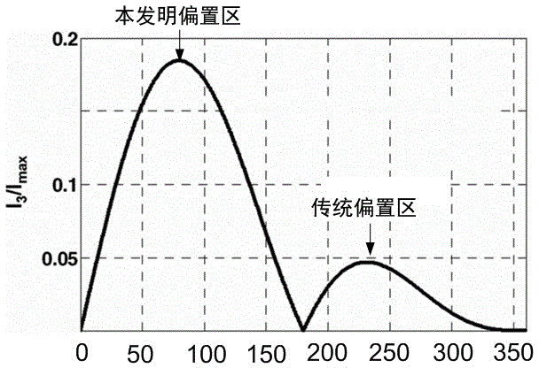
Figure 1 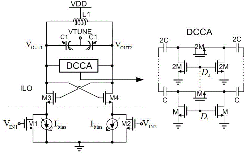
Figure 2 
Figure 3
Abstract
Description
technical field
[0001] The invention belongs to the technical field of integrated circuits, and in particular relates to a low-power injection locked frequency tripler (Injection locked frequency tripler) applied to a radio frequency synthesizer. Background technique
[0002] In today's society, information technology is developing rapidly. With the development of wireless communication technology, the demand for high-speed communication is increasing. However, unlike the low-frequency case, designing a high-frequency receiver presents many challenges, one of which is the design of the frequency synthesizer and its important component, the voltage-controlled oscillator (VCO). Usually a mmWave VCO should be at or close to the similar performance of a low frequency VCO, including lower phase noise, low power consumption, moderate output power, proper regulation range and a relatively low VCO gain (for tuning Capacitance sensitive), in order to make it less restrictive to the...
Examples
Embodiment Construction
[0019] Describe below in conjunction with accompanying drawing:
[0020] Such as figure 1 As shown, the traditional injection-locked tripler circuit consists of L1 and C1 to form a resonant cavity, and cross-coupling tubes M3 and M4 provide negative resistance to maintain oscillation. The signal is input to the gates of the injection transistors M1 and M2 through the off-chip balun, and the third harmonic generated by the transistors M1 and M2 is injected into the resonant cavity through the sources of M3 and M4. At the same time, the transistors M1 and M2 also provide a DC bias for the circuit, so that the entire circuit can start to oscillate normally. figure 2 The efficiency of third harmonic current generation for transistors M1 and M2 as a function of conduction angle. Obviously, in order to obtain a larger third harmonic current and a larger locking range, transistors M1 and M2 should be biased in the weak inversion region ( conduction angle 50~100 degrees). However...