
Low temperature coefficient oscillator
Patent Information
- Authority / Receiving Office
- US · United States
- Current Assignee / Owner
- Publication Date
- 2010-07-08
- Estimated Expiration
- Not applicable · inactive patent
Smart Images
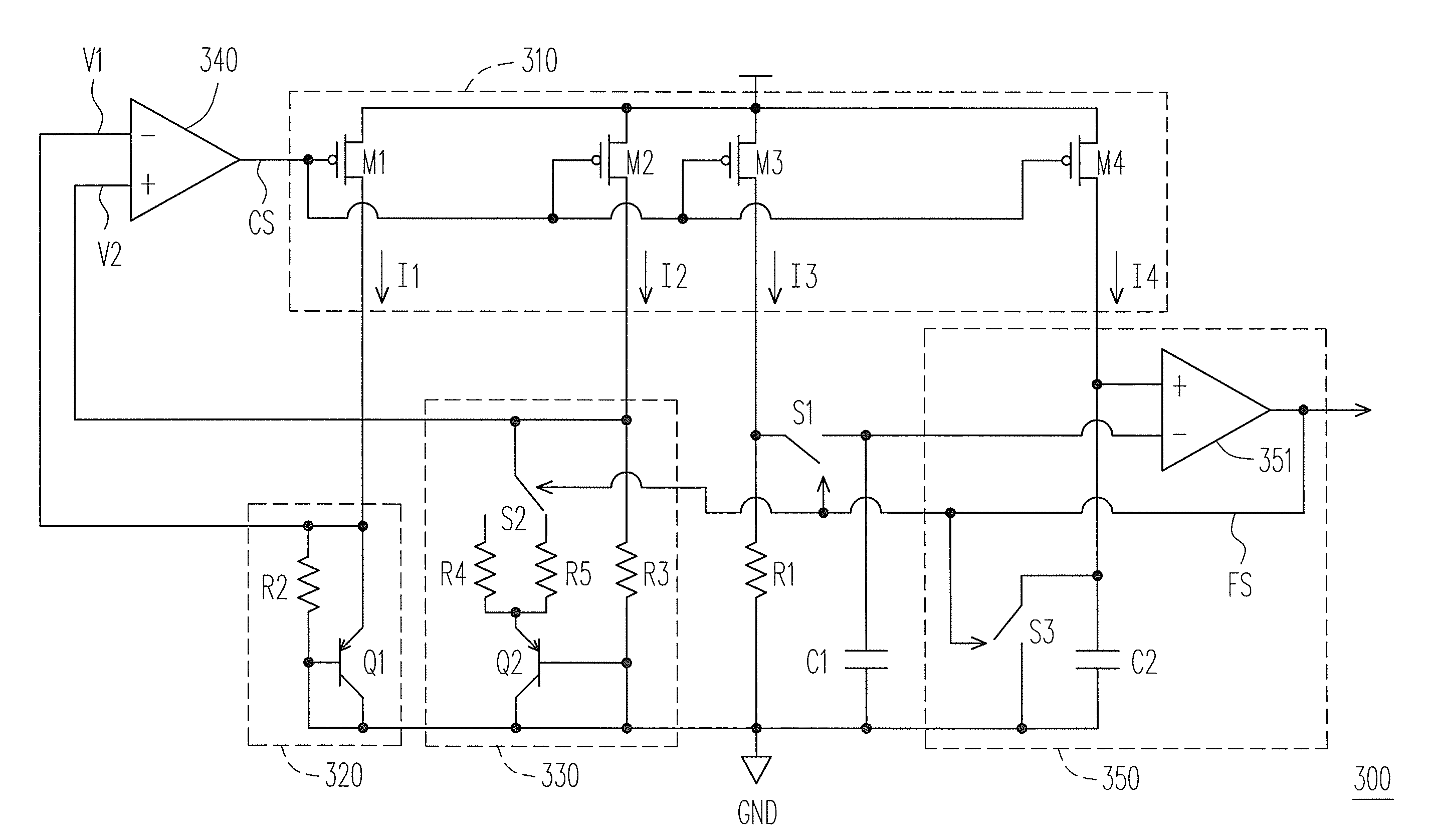
Figure 1 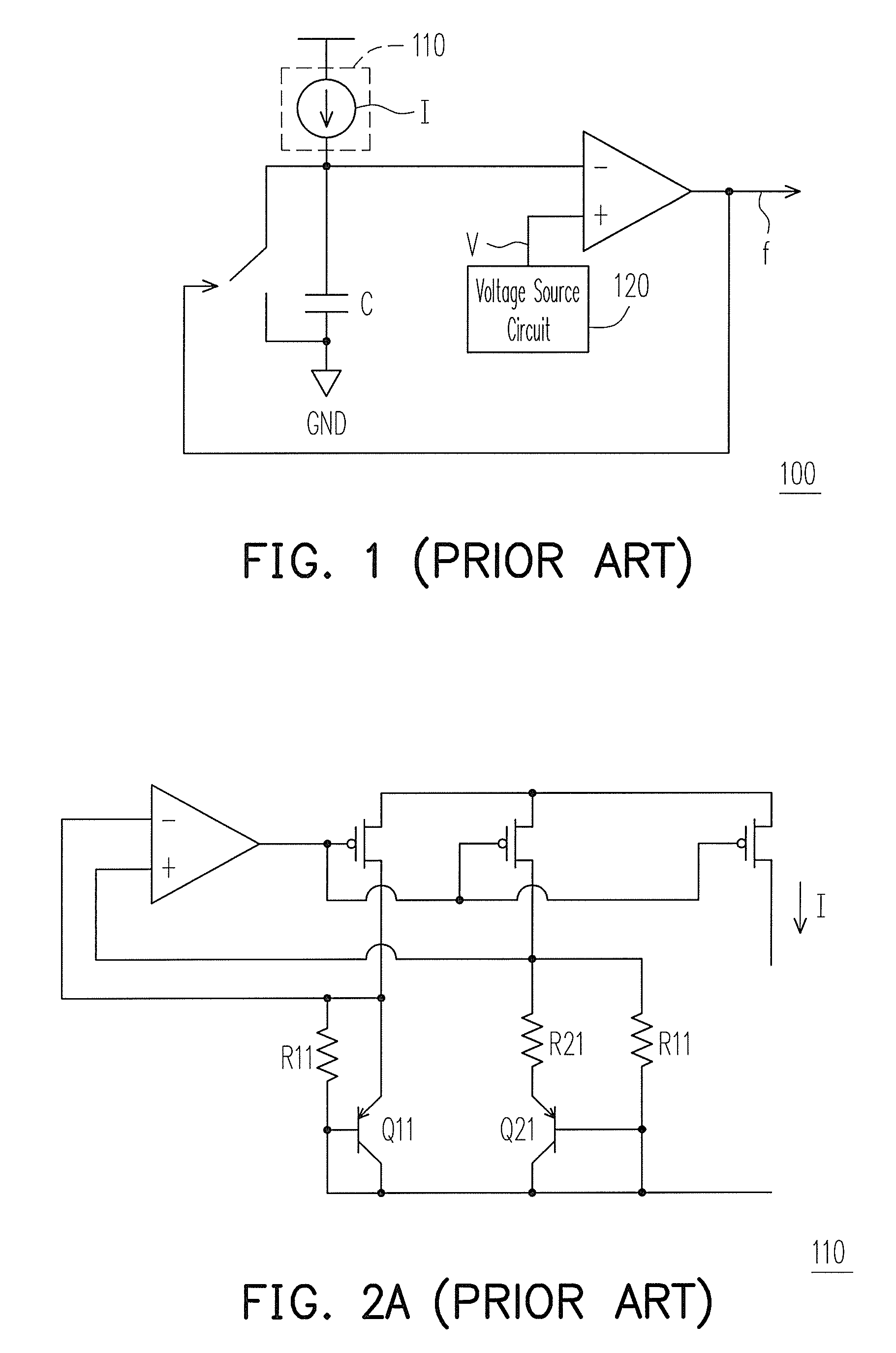
Figure 2 
Figure 3
Abstract
Description
CROSS-REFERENCE TO RELATED APPLICATION
[0001] This application claims the priority benefit of Taiwan application serial no. 98100169, filed Jan. 6, 2009. The entirety of the above-mentioned patent application is hereby incorporated by reference herein and made a part of specification.BACKGROUND OF THE INVENTION
[0002] 1. Field of the Invention
[0003] The present invention relates to an oscillator. More particularly, the present invention relates to a low temperature coefficient oscillator.
[0004] 2. Description of Related Art
[0005] FIG. 1 is a schematic diagram illustrating a conventional silicon oscillator. Referring to FIG. 1, the silicon oscillator 100 charges a capacitor through a current I. When the capacitor is charged to a predetermined voltage V, a switch is triggered and is turned on, so that capacitor is discharged to the ground GND. Then, the switch is turned off, and the capacitor is recharged. By such means, the capacitor is repeatedly charged / discharged, so that the silicon osc...
Examples
Embodiment Construction
[0023]FIG. 3 is a schematic diagram illustrating a low temperature coefficient oscillator according to an embodiment of the present invention. Referring to FIG. 3, the low temperature coefficient oscillator 300 includes a current generator 310, a first voltage generator 320, a second voltage generator 330, an amplifier 340, a first resistor R1, a first switch S1, a first capacitor C1 and an oscillating unit 350.
[0024]The current generator 310 generates a first current I1, a second current I2, a third current I3 and a fourth current I4 according to a control signal CS. The first voltage generator 320 is coupled to the current generator 310, and generates a first voltage V1 according to the first current I1. The second voltage generator 330 is coupled to the current generator 310, and generates a second voltage V2 according to the second current I2 and a frequency signal FS.
[0025]The amplifier 340 generates the control signal CS according to the first voltage V1 and the second voltage...