Method and device for starting working position of apparatus for manufacturing cross winding bobbins

A technology of cross-winding bobbins and working positions, which is applied in the directions of transportation and packaging, thin material handling, and conveying filamentous materials, etc., and can solve the problems of complex devices, no yarn and expensive cross-bobbin replacement devices

A technology of cross-winding bobbins and working positions, which is applied in the directions of transportation and packaging, thin material handling, and conveying filamentous materials, etc., and can solve the problems of complex devices, no yarn and expensive cross-bobbin replacement devices

CN100347062CInactive Publication Date: 2007-11-07RIETER AUTOMATIC WINDER GMBH

Image

  • Method and device for starting working position of apparatus for manufacturing cross winding bobbins
  • Method and device for starting working position of apparatus for manufacturing cross winding bobbins
  • Method and device for starting working position of apparatus for manufacturing cross winding bobbins

Examples


Embodiment Construction

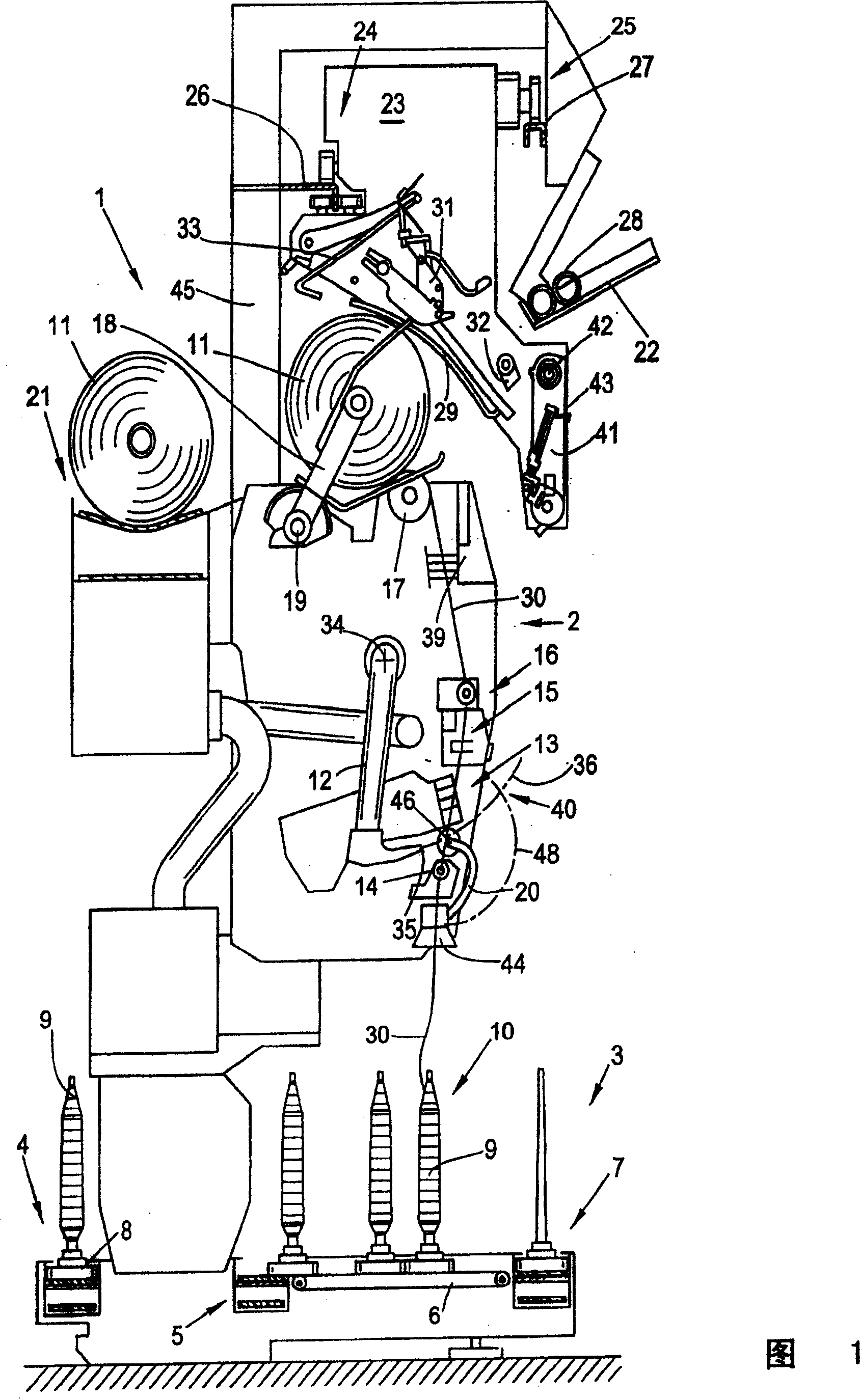
[0023] Figure 1 is a side view of a working position 2 of a textile machine for producing cross-wound bobbins. The textile machine (here a cross bobbin automatic winder) has a plurality of identical working positions between its (not shown) end positions, also referred to below as winder 2 . On these winders 2, as is well known and therefore not described in detail, the yarn feed bobbins, so-called bobbins 9, produced on a ring spinning machine (not shown) are wound into bulky cross bobbins 11. The produced cross bobbins 11 are then loaded onto a cross bobbin conveying device 21 by means of a movable control device, for example by means of a cross bobbin changer 23, and sent to a (not shown) end side of the machine. on bobbin handling stations or similar facilities.

[0024] The cross bobbin automatic winder 1 generally has a logistics device in the form of a bobbin and bobbin delivery system 3 . In the bobbin and bobbin delivery system 3, new cops 9 and unwound empty bobbi...


PUM


Abstract

Process for operating a workstation (2) of a textile machine (1) producing cross-wound bobbins (11), especially in the absence of a thread (30) gripped by a cross-wound bobbin changer (23), comprises picking up the thread of a collecting bobbin using a pneumatically operated gripper tube (20) and transferring the thread into the region of a transfer position lying in the pivot path of the opening of a suction nozzle (12). The opening of the suction nozzle is positioned in the region of the transfer position and the thread is taken over by the suction nozzle loaded with negative pressure. The opening of the suction nozzle is displaced into the region of a thread-handling device of the cross-wound bobbin changer and the thread is transferred to the thread-handling device. The thread is attached to a sleeve provided by the cross-wound bobbin changer using the thread-handling device. An Independent claim is also included for a device for carrying out the above process.

Description

technical field [0001] The invention relates to a method or a device for starting a working station of a textile machine for producing cross-wound bobbins. Background technique [0002] In connection with the work of textile machines for the manufacture of cross-wound bobbins and in particular cross-bobbin automatic winders, it is generally known, for example from DE 4005752 A1, that the bobbins are fed when the yarn breaks or by a computer in relation to the winding position When changing, an automatic device for yarn connection inherent in the working position is activated. [0003] That is to say, firstly a yarn suction nozzle is placed on the surface of the winding bobbin which rotates slowly counter to the winding direction. After detecting the end of the veil, the yarn suction nozzle is returned to its initial position, in which the yarn suction nozzle hole is positioned under a yarn splicing device. The skein of yarn located between the cross bobbin and the suction ...

Claims


Application Information

Patent Timeline
07 Nov 2007
Publication
CN100347062C
IPC
B65H54/26; B65H69/00; B65H67/08; B65H54/06; B65H51/16; B65H54/22; B65H65/00; B65H67/02
CPC
B65H54/26; B65H2701/31; B65H54/06; B65H67/081; B65H67/02; B65H54/707
Inventors
J·珀塞克