Measuring Method of Internal Temperature of Optical Components in Ring Polishing

A technology of optical components and internal temperature, applied in the parts of thermometers, thermometers and thermometers with directly sensitive electrical/magnetic components, etc., can solve the problem that the temperature distribution of optical components cannot be accurately obtained, and achieve a simple measurement process. Convenience, deterministic control, and improved measurement accuracy

Active Publication Date: 2021-06-22
HARBIN INST OF TECH
View PDF0 Cites 0 Cited by
  • Summary
  • Abstract
  • Description
  • Claims
  • Application Information

AI Technical Summary

Problems solved by technology

[0004] The purpose of the present invention is to provide a method for measuring the internal temperature of the optical element in the ring polishing process in order to overcome the problem that the internal temperature distribution of the optical element cannot be accurately obtained during the ring polishing process

Method used


Image

  • Measuring Method of Internal Temperature of Optical Components in Ring Polishing
  • Measuring Method of Internal Temperature of Optical Components in Ring Polishing
  • Measuring Method of Internal Temperature of Optical Components in Ring Polishing

Examples


specific Embodiment approach 1

[0015] The method for measuring the internal temperature of the optical element in the ring polishing process of the present invention, the specific steps are as follows,

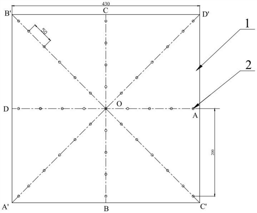
[0016] Step 1: A plurality of blind holes are drilled on the temperature collecting body 1 of the optical element as the temperature collecting hole 2, and the plurality of temperature collecting holes 2 are uniformly arranged in a concentric circular array with the center point of the temperature collecting body 1 of the optical element as the center of the circle. At the same time, the temperature collection holes 2 are also distributed along multiple radii of the concentric ring array; except the temperature collection hole 2 on the center of the circle, the temperature collection holes 2 located on the same radius of the concentric ring array form a group. The temperature collection holes 2 within the group have the same depth, and the two groups of temperature collection holes 2 located on the same diam...

specific Embodiment approach 2

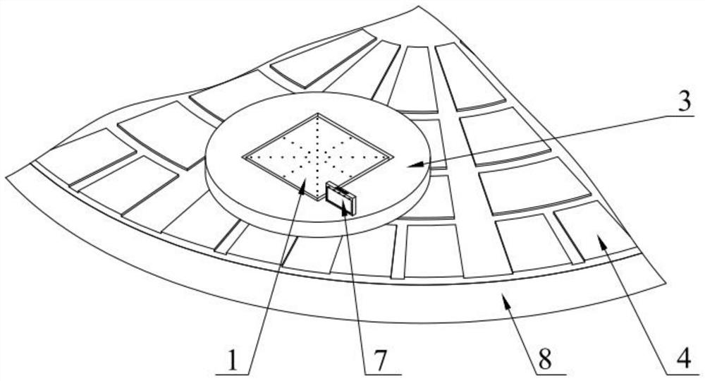
[0023] The difference between the second embodiment and the first embodiment is that in the second step, the temperature acquisition device is used to collect the temperature value at the bottom of each temperature acquisition hole 2: as figure 2 with image 3 as shown,

[0024] The temperature acquisition device includes a plurality of temperature sensors 5 and a recorder 7; the number of temperature sensors 5 is equal to the number of temperature acquisition holes 2;

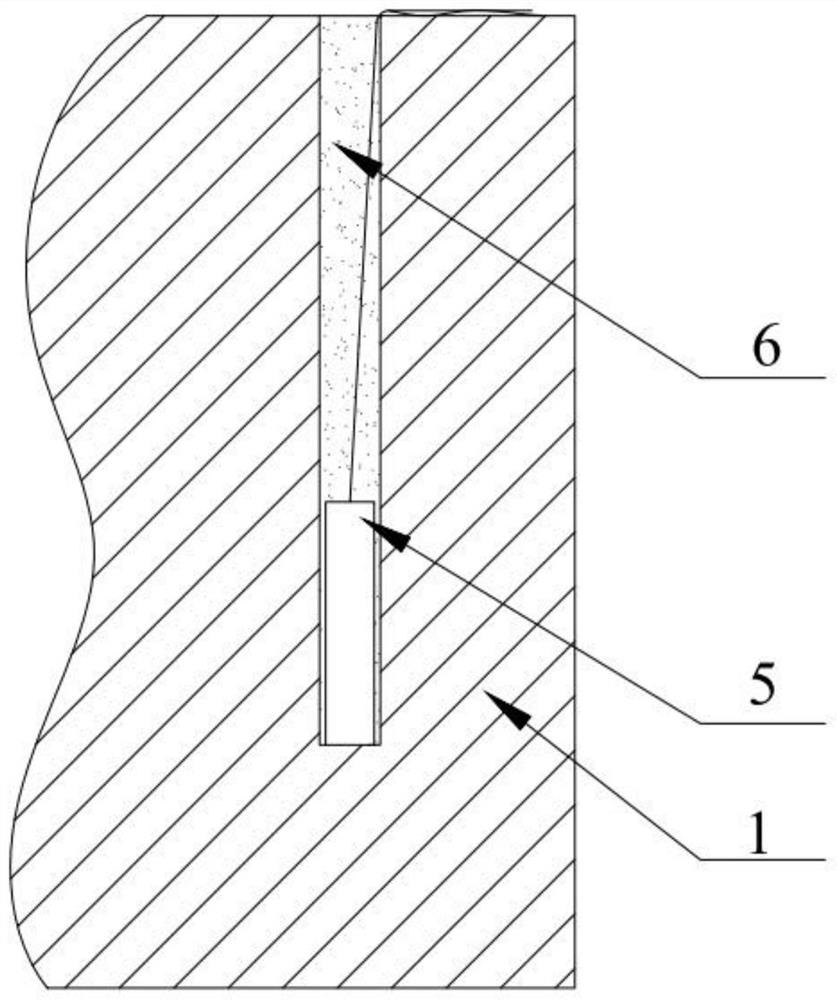
[0025] Insert the measurement ends of multiple temperature sensors 5 into multiple temperature collection holes 2 respectively, and make the measurement ends contact the bottom surface of temperature collection holes 2;

[0026] Fill the heat insulating material 6 in the temperature collection hole 2, so that the measuring end of the temperature sensor 5 is fixed in the temperature collection hole 2;

[0027] The recorder 7 is fixed on the retaining ring 3 for receiving the temperature signals collected by ...

specific Embodiment approach 3

[0029] The difference between the third embodiment and the first or second embodiment is that, as figure 1 As shown, the cross section of the optical element temperature collecting body 1 is square or circular.

[0030] The square has a side length of 430 mm and a thickness of 80 mm.

[0031] On the basis that the cross-section of the temperature collecting body 1 of the optical element is square, the eight radii of the concentric rings respectively fall on the two vertical midlines and the two diagonal lines of the temperature collecting body 1 of the optical element.

[0032] Such as figure 1 As shown, the temperature collection hole 2 is divided into multiple groups, wherein the midpoint O on the upper surface of the temperature collection body 1 of the optical element is used as the dividing point, and the two vertical midlines and two diagonal lines are divided into eight lines, namely OA and OB. , OC, OD, OA', OB', OC', OD', the broken lines formed by each half of the ...


PUM


Abstract

The method for measuring the internal temperature of the optical element in the ring polishing process of the present invention relates to a temperature measurement method of the optical element, the purpose is to overcome the problem that the internal temperature distribution of the optical element cannot be accurately obtained during the ring polishing process, the specific steps are as follows, step 1 1. Set the temperature collection hole in advance; Step 2: Turn on the ring polishing machine and measure the temperature. The invention aims at the difficult problem of measuring the temperature of the processing surface in the ring polishing process, and according to the characteristics of uniform distribution of the internal temperature of the glass element in a single direction, the complete internal temperature distribution data of the rectangular glass element is obtained; the glass element, especially the rectangular glass element, is obtained by the method of the present invention The internal temperature distribution of the glass element can be inferred, and the shape change process of the glass element heated during processing can be inferred, so that the parameters of the ring polishing process can be adjusted to achieve deterministic control of the rectangular glass element.

Description

technical field [0001] The invention relates to a method for measuring the temperature of an optical element, in particular to a method for measuring the temperature in the thickness direction and the horizontal direction of the optical element during the ring polishing process. Background technique [0002] Large glass ring polishing machine is a kind of equipment used for precision polishing of the plane of large optical glass components. For large-diameter glass components, due to their own gravity, there will be friction between them and the polishing disc during processing, which will generate heat. This heat will increase the local temperature of large optical glass components and cause deformation. [0003] However, during the ring polishing process of optical components, the temperature distribution inside the component cannot be accurately obtained, and the temperature field of the component cannot be controlled, which leads to deformation of the optical glass compo...

Claims


Application Information

Patent Timeline
Patent Type & Authority Patents(China)
IPC IPC(8): G01K7/18G01K1/14
CPCG01K1/14G01K7/18
Inventor 王乙任廖德锋张飞虎
Owner HARBIN INST OF TECH
Why Eureka
Try Eureka