Starting speed regulator of liquid resistance in use for squirrel cage motor

A technology of liquid resistors and motors, which is applied in the direction of motor generators/starters, liquid resistors, starters of single multi-phase induction motors, etc. It can solve the problems of cage motor applications, insulation and safety, and speed regulation technology cannot And other issues

Inactive Publication Date: 2008-06-25
何起军 +1
View PDF3 Cites 2 Cited by
  • Summary
  • Abstract
  • Description
  • Claims
  • Application Information

AI Technical Summary

Problems solved by technology

Due to the existence of this high voltage, the technical problems of insulation and safety make the original speed regulation technology unable to be applied to cage motors

Method used


Image

  • Starting speed regulator of liquid resistance in use for squirrel cage motor

Examples


Embodiment Construction

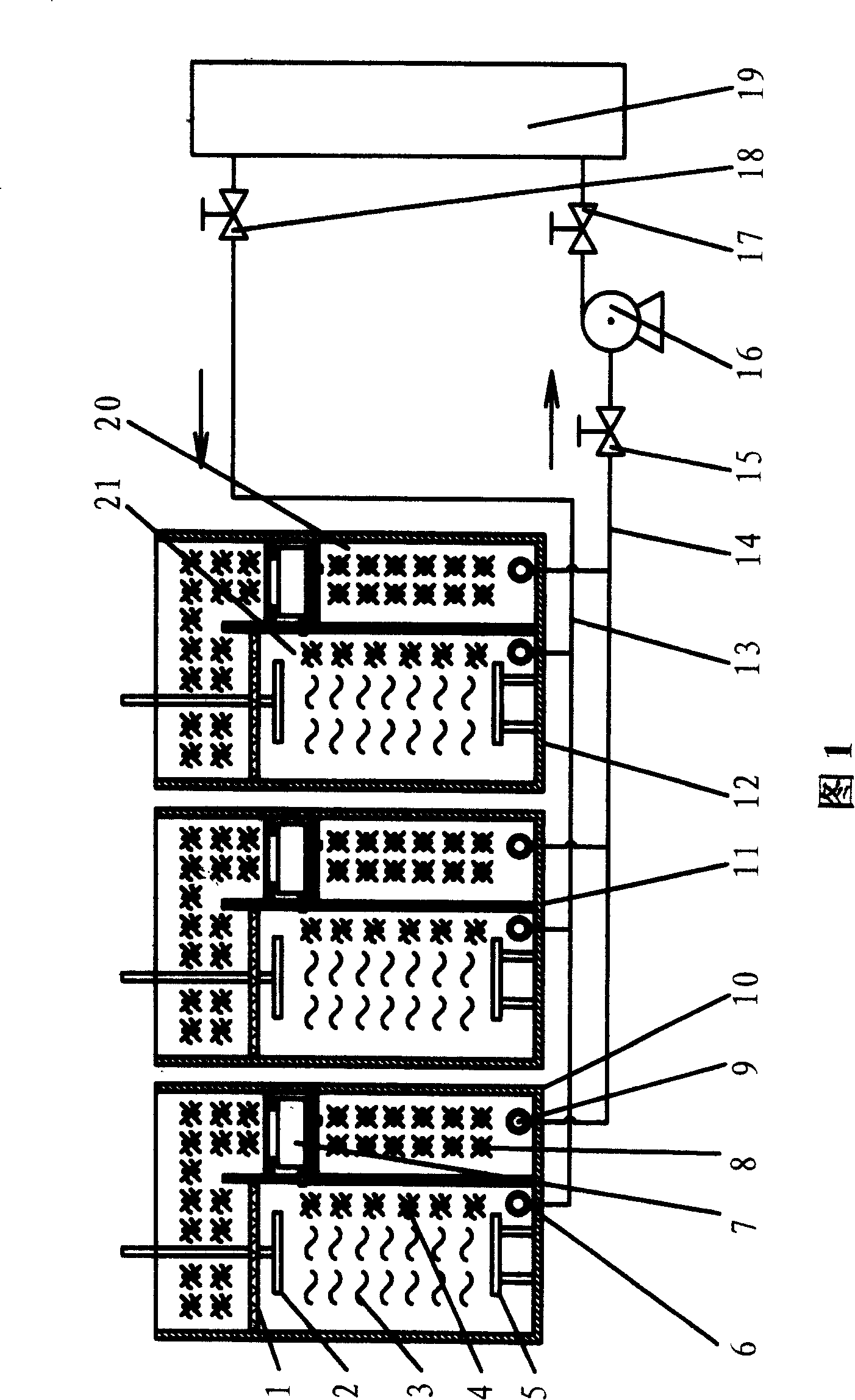
[0010] As shown in Figure 1. Cabinet body, liquid resistance box 10, 11, 12 box body, moving pole plate 2, static pole plate 5, radiator 19, valve 15, 17, 18, water pump 16, transmission mechanism are all the same as in the existing liquid resistance governor The corresponding is the same. The vertical partition divides the liquid resistance box into a liquid resistance chamber 21 and a slow flow chamber 20. The upper part of the liquid resistance chamber 21 is provided with a filter layer 1 arranged horizontally, and the moving plate 2 and the static plate 5 are arranged in the liquid chamber below the filter layer 1. In the resistance storehouse 21, the electro-hydraulic 3 is housed in the liquid resistance storehouse 21. The lower part of the liquid resistance chamber 21 is provided with a coolant inlet 6 . The upper part of the slow flow chamber 20 is provided with double-layered horizontally arranged closed partitions, and an oil-water separator 7 is installed between t...


PUM


Abstract

The invention is designed for solving the problem of which the liquid resistor currently used in the squirrel cage motor always carries high voltage so as to threaten the human safety. It comprises a cabinet, a liquid resistor tank located on the moving pole plate and the fixed pole plate, a driver mechanism for driving the pole plates to make up and down movement, and a cooling system. The liquid resistor tank is separated by a stick up plate into a liquid resistor chamber and a slack flow chamber. On the upper portion of the liquid resistor chamber, there is a filter layer, and on the upper portion of the slack flow chamber, there is an oil-water separator; the water outlet is connected to the liquid resistor chamber; the oil outlet is connected to the slack flow chamber. The input pipe and outlet pipe all are made of high pressure resistance materials, and are respectively connected to the entrance and the exit of cooling agent. The cooling system uses high pressure resistance cooling agent.

Description

technical field [0001] The invention relates to a liquid resistance starting speed regulating device for a motor, in particular to a liquid resistance starting speed regulating device suitable for squirrel-cage high and low voltage motors. The invention belongs to the technical field of motor liquid resistance start speed regulation. Background technique [0002] The existing liquid resistance speed control technology is mainly used for wound-type motors. The principle is to connect the liquid resistance in series with the rotor of the wound-type motor through the three-phase moving plate and the fixed plate, so as to adjust the speed of the moving plate. The distance between the two plates is used to adjust the resistance value of the liquid resistance, that is, the farther the distance between the two plates, the greater the resistance value, the smaller the current through the liquid resistance and the motor winding, and the lower the motor speed; The closer the distance...

Claims


Application Information

Patent Timeline
Patent Type & Authority Patents(China)
IPC IPC(8): H02P1/36H01C10/02
Inventor 何起军闫建珍
Owner 何起军
Why Eureka
Try Eureka