Heat exchanger in particular for an evaporator of a vehicle air-conditioning unit

A technology for heat exchangers and devices, applied in evaporators/condensers, heat exchange equipment, refrigerators, etc., can solve problems such as narrow manufacturing tolerances, and achieve the effects of reducing total cost, low defective rate, and light weight

Inactive Publication Date: 2009-07-08
BEHR GMBH & CO KG
View PDF8 Cites 1 Cited by
  • Summary
  • Abstract
  • Description
  • Claims
  • Application Information

AI Technical Summary

Problems solved by technology

[0004] A disadvantage of prior art heat exchangers is that manufacturing tolerances must be rather narrow in order to minimize the chance of defective products

Method used


Image

  • Heat exchanger in particular for an evaporator of a vehicle air-conditioning unit
  • Heat exchanger in particular for an evaporator of a vehicle air-conditioning unit
  • Heat exchanger in particular for an evaporator of a vehicle air-conditioning unit

Examples


Embodiment Construction

[0067] A first embodiment of the heat exchanger of the invention is configured as an evaporator for an air-conditioning system of a motor vehicle, hereinafter referred to Figure 1-7 to describe in detail.

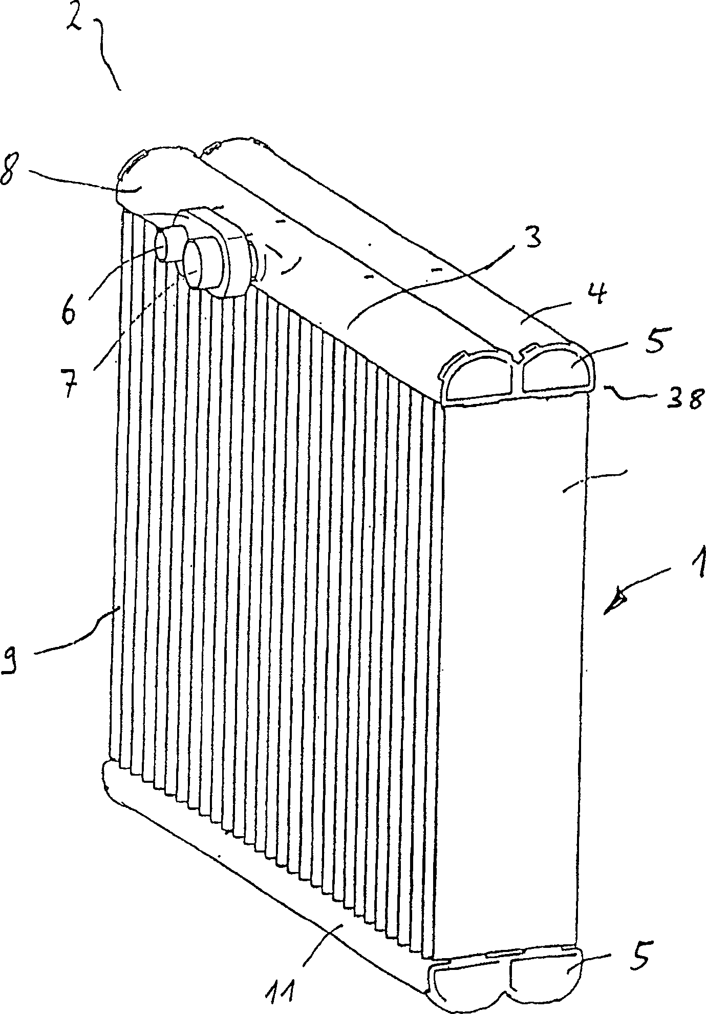
[0068] figure 1 The heat exchanger shown in the perspective view includes an upper header box 2 and a lower header box 11, with heat transfer tubes 9 disposed therebetween.

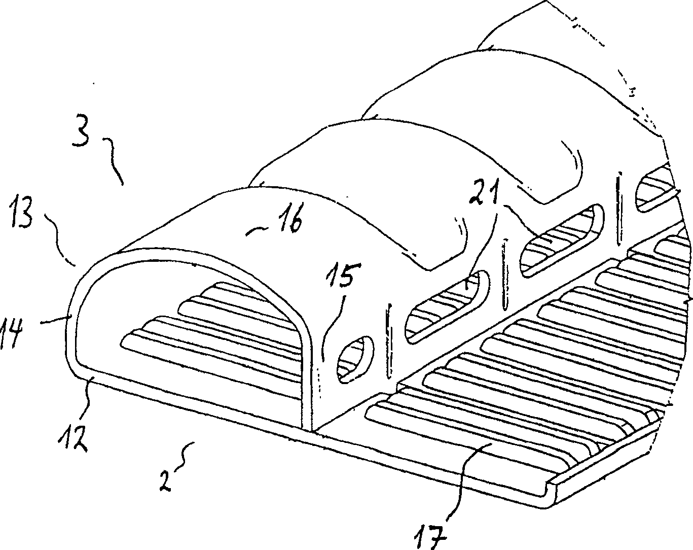
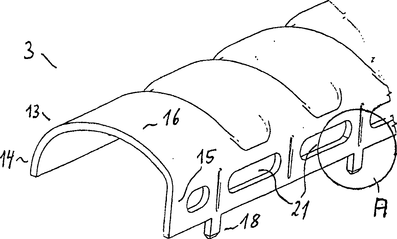
[0069] The upper header box 2 includes a first header chamber 3 and a second header chamber 4 parallel thereto, and the end surface of the header chamber is closed by a cover 5 . An inlet 6 and an outlet 7 for evaporating coolant are arranged on one longitudinal side 8 of the first header tank 3 .

[0070] However, it should be pointed out that the inlet and outlet can be provided not only on one or both header tank longitudinal sides 8 of the header tank 3, but it is also possible to arrange the inlet on the first header tank longitudinal side and the outlet on the longitudinal side 8 of the first ...


PUM


Abstract

A heat exchanger for heat transfer, in particular an evaporator for an air conditioning system of a motor vehicle, comprising: at least one header tank having at least two header chambers, wherein substantially each header chamber Approximately defined by a base member and a top member. The top device includes intermediate sidewalls. At least a portion of the intermediate sidewalls are positioned proximate to each other. The spacing between the two intermediate sidewalls increases with height above the base device.

Description

technical field [0001] The invention relates to a heat transfer device, in particular to an evaporator, in particular for an air-conditioning system of a motor vehicle, having at least one header box comprising at least two header chambers. Although the invention has been described with reference to an evaporator of an air-conditioning system of a motor vehicle, the invention is not limited to this use, but can be used in other air-conditioning devices and the like. Background technique [0002] Heat exchangers of the above type are known in the prior art. DE 19826881 A1 discloses a heat exchanger with header tanks made of sheet metal made of pretreated plates. The header box is divided longitudinally into two chambers, in which the ends of two rows of flat tubes arranged in series are inserted into the base section or plate of the header box, through which the air flowing is cooled. The header chambers comprise side walls, wherein adjacent side walls of two header chamber...

Claims


Application Information

Patent Timeline
Patent Type & Authority Patents(China)
IPC IPC(8): F28D1/053F28F9/02F25B39/04F28F1/02B60H1/32F25B39/02
CPCF28D1/05391F28F9/0214F25B39/02F28F1/022F28D2021/0085F28D1/0535
Inventor G·迪尔K·弗尔斯特尔F·奥特W·泽瓦尔德
Owner BEHR GMBH & CO KG
Why Eureka
Try Eureka