Method for producing a variable turbine geometry

A turbine, variable technology, applied in the direction of stator, engine components, machine/engine, etc., can solve the problem that the gap cannot be optimally minimized, and achieve the effect of increasing power and accurate spacing

Active Publication Date: 2016-08-03
BOSCH MAHLE TURBO SYST GMBH & CO KG
View PDF6 Cites 0 Cited by
  • Summary
  • Abstract
  • Description
  • Claims
  • Application Information

AI Technical Summary

Problems solved by technology

Therefore, the clearance cannot be minimized optimally, especially since the operability of the variable turbine geometry has to take into account the possible maximum tolerance deviation

Method used


Image

  • Method for producing a variable turbine geometry
  • Method for producing a variable turbine geometry

Examples


Embodiment Construction

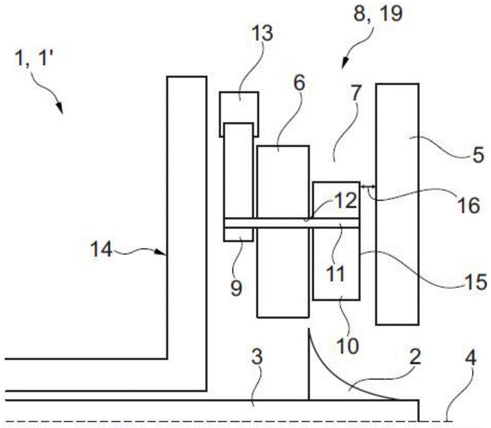
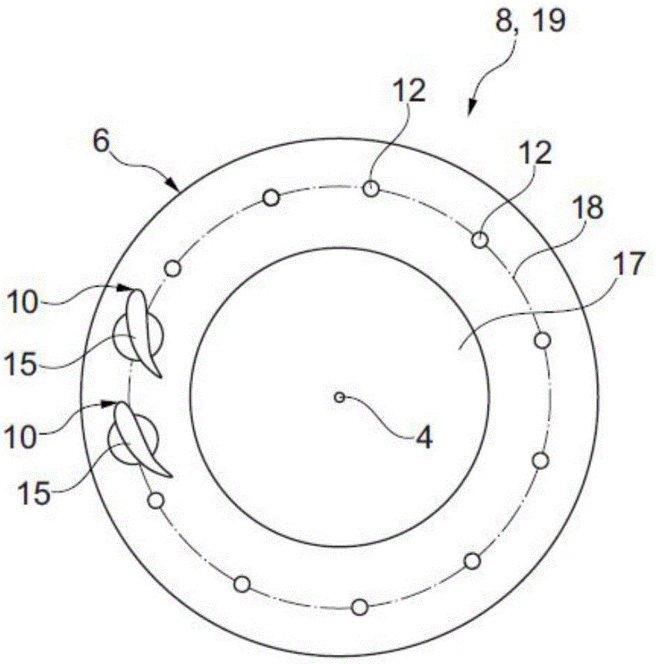
[0027] figure 1 A section through the charging device 1, in particular the exhaust gas turbocharger 1' is shown, wherein the charging device 1 is only partially visible. The charging device 1 has a turbine 2 connected to a shaft 3 for rotation therewith. The turbine 2 and the shaft 3 are rotatable about the axis of rotation 4 , wherein only the upper part of the charging device 1 is visible relative to the axis of rotation 4 . The rotation of the turbine 2 can be transmitted by means of a shaft 3 to a compressor wheel (not shown) of the charging device 1 . Here, the turbine 2 is driven by a fluid, in particular by exhaust gas generated from the internal combustion engine and flowing to the turbine 2 through a duct 7 formed between the cover disk 5 and the blade mounting ring 6 . The blade mounting ring 6 is part of a variable turbine geometry 8 which additionally has an adjusting ring 13 arranged on the side of the blade mounting ring 6 facing away from the duct 7 and at lea...


PUM


Abstract

The invention relates to a method for producing a variable turbine geometry (8) of a charging device (1). The variable turbine geometry (8) has a plurality of guide blades (10) which are arranged on a blade mounting ring (6). Herein that at least two guide blades (10) are inserted into the blade mounting ring (6) is essential for the invention, and then in the mounting state, the at least two guide blades (10) are jointly processed on respective end side (15) facing away from the blade mounting ring (6) in order to produce a final shape of the end sides (15). Furthermore the invention relates to the variable turbine geometry (8), and a charging device (1) with the variable turbine geometry (8), and particularly to an exhaust gas turbocharger (1').

Description

technical field [0001] The invention relates to a method of manufacturing a variable turbine geometry for a charging device and to said variable turbine geometry. Furthermore, the invention relates to a charging device, in particular an exhaust gas turbocharger, having said variable turbine geometry. Background technique [0002] Charging devices, in particular exhaust gas turbochargers, are known from the prior art. In this case, the turbine is driven by the drive fluid, in particular by the exhaust gas, and transmits said drive force via a shaft to the compressor wheel. In order to increase the power of the driven machine, in particular at different operating points, it is also known to provide the charging machine with a variable turbine geometry having a large number of guide vanes around the turbine. Here, the flow of the drive fluid, that is to say in particular the exhaust gas, to the turbine can be influenced by means of the guide vanes. In this case, for example,...

Claims


Application Information

Patent Timeline
Patent Type & Authority Applications(China)
IPC IPC(8): F01D17/16F01D9/04F01D17/14F02B37/24
CPCF01D9/042F01D17/14F01D17/16F02B37/24F05D2230/60F01D17/165F05D2220/40Y02T10/12B23P15/02F01D9/041F05D2240/12F05D2240/80
Inventor 茵·迪克·瑙恩海姆M.·恩·达朗·布勒布勒安
Owner BOSCH MAHLE TURBO SYST GMBH & CO KG
Why Eureka
Try Eureka