Rotor shaft module, rotor shaft, compact circuit breaker and method for producing rotor shaft module

A technology of power switch and rotor shaft, which is applied to the parts of protection switch, electric switch, protection switch, etc. It can solve the problems of unreliable transmission, damage of coupling device, failure of compact power switch, etc., and achieve the effect of reliable circuit breaker

Inactive Publication Date: 2015-09-30
SIEMENS AG
View PDF3 Cites 1 Cited by
  • Summary
  • Abstract
  • Description
  • Claims
  • Application Information

AI Technical Summary

Problems solved by technology

However, due to these small production tolerances, in particular in order to avoid pre-damages at the connection due to these small tolerances, it is necessary to take measures when manufacturing and installing the rotor shaft module of the compact power switch. troublesome measures
In order to transmit the occurring rotational forces, tolerances that are partly already so small are required during the manufacture of the rotor shaft module that, when the rotor shaft module is installed as a rotor shaft only slightly imperfectly or only carelessly, Damage to the coupling
In addition, the maximum transmittable rotational force between the individual rotor shaft modules is limited due to the use of plastic
However, this also limits the magnitude of current or the level of power that can be converted by the compact power switch
The reason for this is that higher currents or higher powers also result in higher current intensities, wherein the resulting higher torques are no longer available in the worst case when the compact power switch is disconnected. cannot be reliably transmitted via the connection between the individual rotor modules of the rotor shaft of the compact power switch
As a result, failure of the compact power switch at higher currents or higher current outputs cannot be reliably ruled out.

Method used


Image

  • Rotor shaft module, rotor shaft, compact circuit breaker and method for producing rotor shaft module
  • Rotor shaft module, rotor shaft, compact circuit breaker and method for producing rotor shaft module
  • Rotor shaft module, rotor shaft, compact circuit breaker and method for producing rotor shaft module

Examples


Embodiment Construction

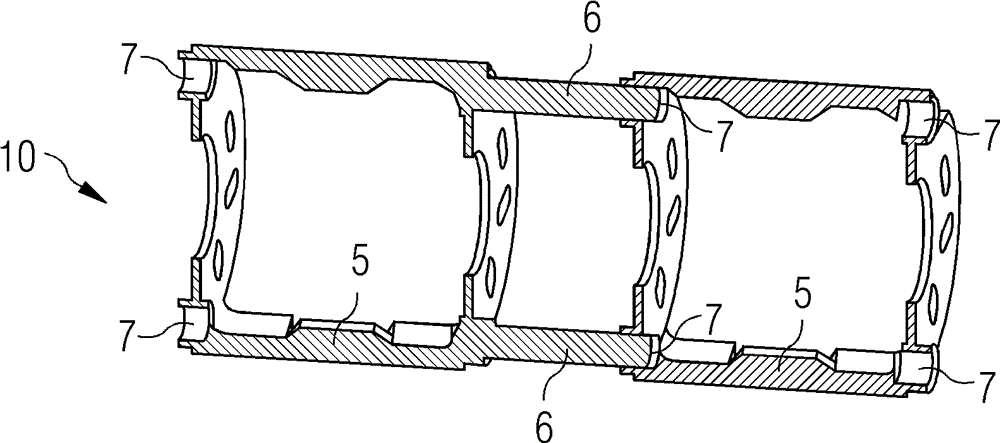
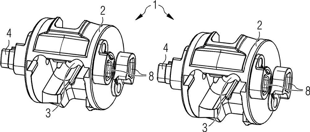
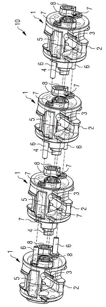
[0046] figure 1 A compact power switch 20 according to the invention is shown. The compact power switch 20 here has a locking mechanism 22 which is designed in particular for actuating a contact system 24 . The contact system 24 here comprises a fixed contact 23 and a contact element 21 for each individual phase which can be switched by the compact power switch 20 , wherein figure 1 One of these contact systems 24 can be seen in . The contact element 21 is arranged here in the rotor shaft module 1 of the rotor shaft 10 of the compact power switch 20 . By rotating the rotor shaft 10 , the contact elements 21 and the fixed contacts 23 can be brought into contact, whereby the contact system 24 is closed and current can flow. In this case, the compact power switch 20 is designed to switch a plurality of phases, which can be seen by a plurality of first connections 25 and second connections 26 . By actuating the locking mechanism 22 , all contact systems 24 of the individual ph...


PUM


Abstract

A rotor shaft module for a rotor shaft of a molded-case circuit breaker, includes a module body including an electrically insulating first material, the module body including a receptacle for a contact element of the molded-case circuit breaker. The rotor shaft module includes at least one coupling apparatus for connection to an opposing coupling apparatus of a further rotor shaft module. In addition, disclosed are a rotor shaft for a molded-case circuit breaker includes at least two coupled rotor shaft modules; a molded-case circuit breaker including a rotor shaft; and a method for producing a rotor shaft module for a rotor shaft of a molded-case circuit breaker.

Description

technical field [0001] The invention relates to a rotor shaft module for a rotor shaft of a compact power switch, the rotor shaft module having a module body made of a first electrically insulating material, wherein the module body has a a receptacle for a contact element of a power switch, and the rotor shaft module has at least one coupling device for connection to a mating coupling device of another rotor shaft module. Furthermore, the invention relates to a rotor shaft for a compact power switch, a compact power switch with a rotor shaft and a method for producing a rotor shaft module for a rotor shaft for a compact power switch. Background technique [0002] In modern technology, compact power switches (MCCB=Molded Case Circuit Breaker) are known and widely used. Such compact power switches are especially capable of switching relatively high currents or powers. Since such compact power switches are often also provided with safety devices, such as overload protection a...

Claims


Application Information

Patent Timeline
Patent Type & Authority Applications(China)
IPC IPC(8): H01H1/22H01H11/00
CPCH01H2009/0094H01H71/0257H01H1/2041H01H71/0235H01H2221/056H01H2205/002Y10T29/49105H01H9/00H01H11/00H01H1/2058H01H19/10
Inventor J-U.达尔E.戴利茨W.埃文B.格尔克A.库普施
Owner SIEMENS AG
Why Eureka
Try Eureka