System and method for intraluminal imaging

a technology of intraluminal imaging and system, applied in the field of catheter systems, can solve the problems of limited blood flow, serious health risks, power loss and other inefficiencies inherent in catheter transmission,

Inactive Publication Date: 2002-07-16
BOSTON SCI SCIMED INC
View PDF38 Cites 69 Cited by
  • Summary
  • Abstract
  • Description
  • Claims
  • Application Information

AI Technical Summary

Benefits of technology

The present invention is directed to an improved catheter system having a work element coupled to a drive cable disposed within a lumen of a flexible tubular catheter body. The work element generally includes an ultrasonic imaging transducer. One advantageous improvement described in more detail below, includes a reconfiguration of ferrites in the hub assembly, such that a gap, typical between the ferrites, is reduced or eliminated. In reducing or eliminating the gap it is meant that the average clearance between two facing surfaces of the ferrites will be less than 0.0005 in., preferably less than 0.0002 in., and most preferably less than 0.0001 in. In reducing or eliminating the gap clearance in this manner, manufacture of the hub assembly can be done with less precision, which makes the overall fabrication process simpler and less expensive. Moreover, by reducing or eliminating the gap clearance, the inductive transmission of the electrical signal can be accomplished with more efficiency and with reduced transmission losses.
In yet another aspect, an improved catheter system of the type including (a) a tubular catheter body having a proximal portion, a distal portion, and a primary lumen therethrough; and (b) a drive cable having a cable body and a cable lumen rotatably received in the primary lumen, where the drive cable has at least one lead wire disposed in the cable lumen, is provided. The improvement includes a strain relief device coupled to a portion of the drive cable. The strain relief device causes the lead wires to be biased, typically with a spring or similar device, such that the lead wires can extend or retract from within the drive cable. The movement of the lead wires keeps the lead wire from being directly subjected to tensile forces which may cause the lead wires to break.

Problems solved by technology

Blood flow is restricted and the person's health is at serious risk.
However, as in most rotary transformers, there are losses of power and other inefficiencies inherent in this transmission.
For example, it is generally difficult without labor intensive and expensive manufacturing processes, to provide a consistent gap size.
Moreover, it can be difficult to ensure that the rotating ferrite rotates with enough precision to avoid inadvertently contacting the fixed ferrite.
One potential drawback to the drive cable described above is its susceptibility to stretching.
While a stretchable drive cable may be advantageous for some purposes, it can also be problematic.
Transducer lead wires, disposed and anchored within the drive cable lumen, do not have the ability to stretch and when subjected to tensile forces, the transducer lead wires tend to break which creates a break in the electrical continuity of the system.
Generally, the side exit port works well, however, the side exit port can be a nuisance in a clinical setting since it is difficult to know which way the side exit port is pointing during flushing procedures.
The coils may either expand or contract as the drive cable rotates which increases the interference between the multiple layers and thus increases the torque transmission capability of the drive cable.

Method used


Image

  • System and method for intraluminal imaging
  • System and method for intraluminal imaging
  • System and method for intraluminal imaging

Examples


Embodiment Construction

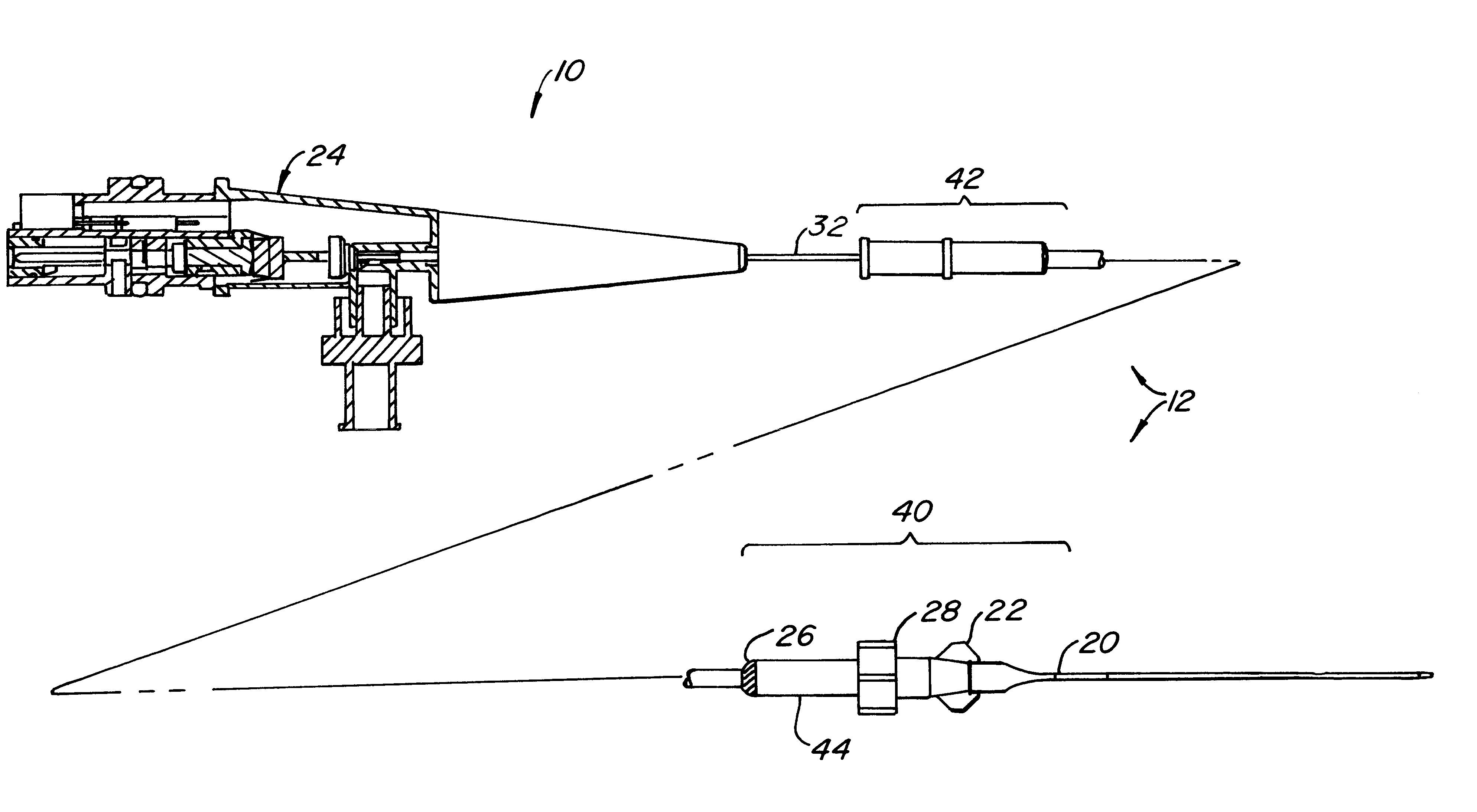
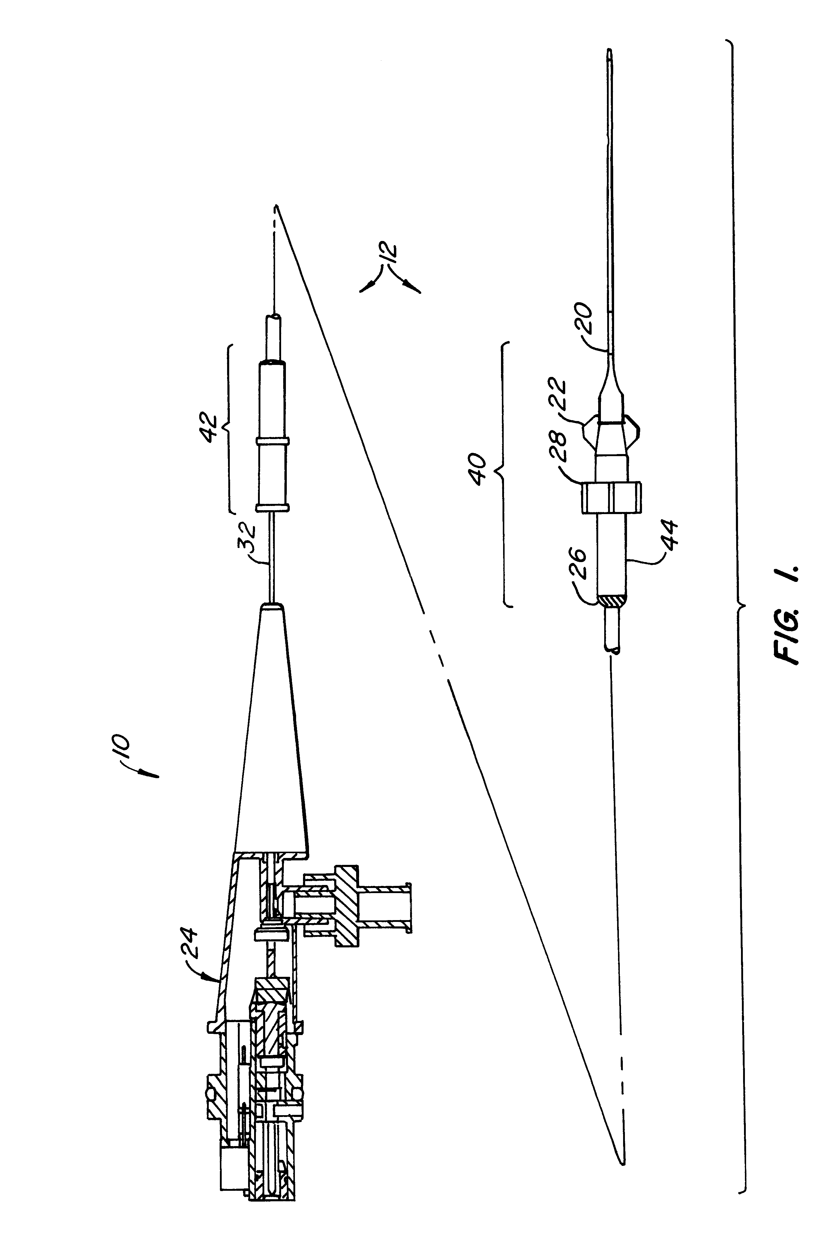
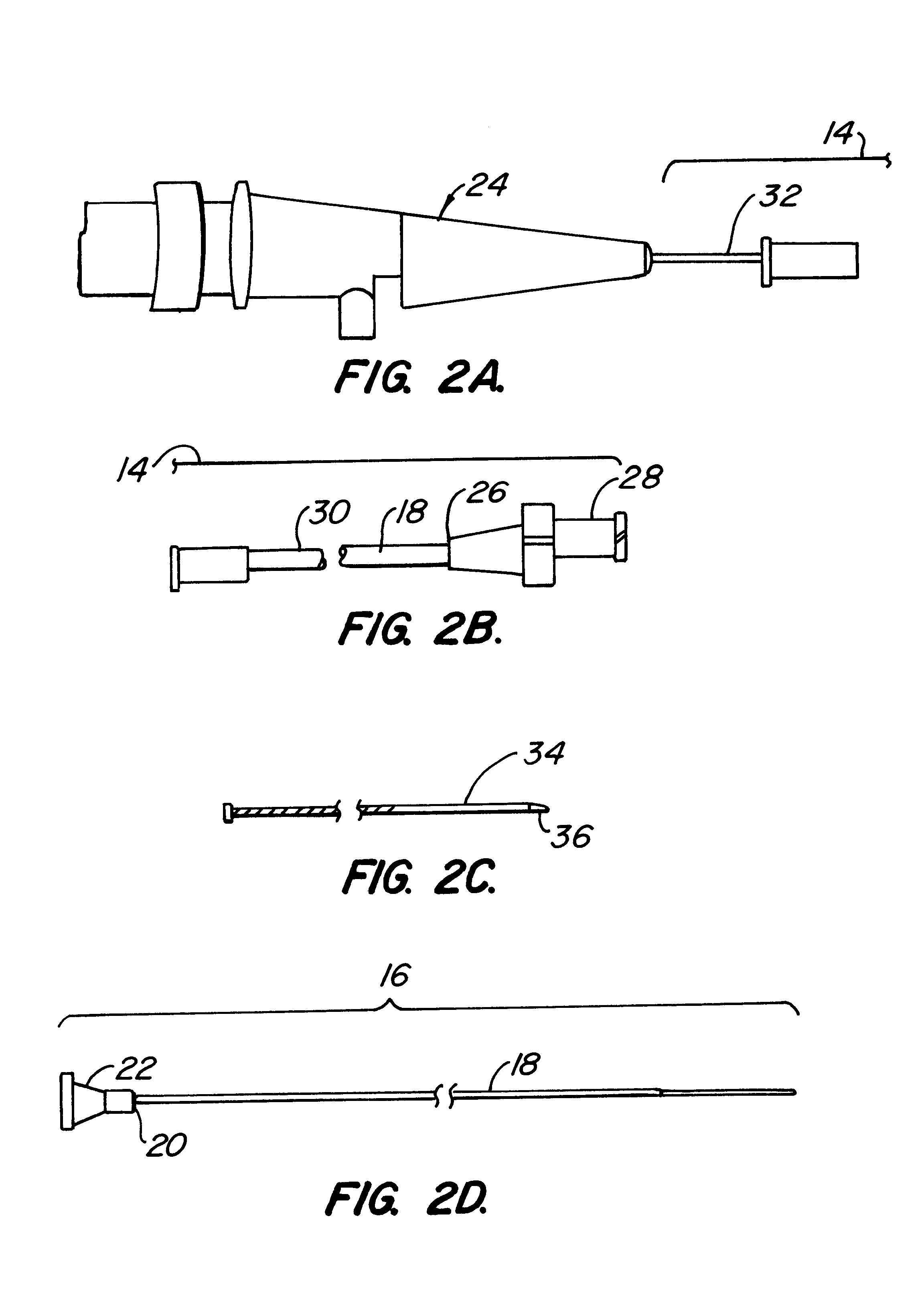
A vascular catheter system is provided having a catheter body with a proximal portion and a distal portion, both having a proximal end, a distal end and a primary lumen therebetween. This distal portion further includes a guidewire lumen preferably disposed coaxial with, and distal to the primary lumen. A drive cable is disposed within the primary lumen, which is usually axially translatable within the lumen and rotatable about its own longitudinal axis. The drive cable carries a work element at its distal end, typically being an ultrasonic imaging transducer, but optionally being an interventional device. The outer diameter of the drive cable may be varied to accommodate variations in size of the catheter body.

Provided at the proximal end of the drive cable is a tuning hub assembly. The hub assembly, among other things, provides the ability to match the impedance between a transmitter / receiver and the work element. In some cases, the work element may be an ultrasonic transducer, wh...


PUM


Abstract

An improved catheter system having an ultrasonic imaging transducer coupled to a drive cable disposed within a lumen of a flexible tubular catheter body. An improvement including a reconfiguration of the ferrites in the hub assembly, such that the need for the gap between the ferrites is removed. A strain relief member is provide to increase the strength of the electrical transmission lines to enable them to withstand the tensile forces caused by either flushing and / or pull-back operations. A device which allows the electrical transmission lines to extend their length when placed in tension may also be employed to provide strain relief to the electrical transmission lines. Another improvement includes a counter-wound coil structure, which may either expand or contract as the drive cable is being rotated to strengthen the drive cable. The distal tip of the catheter body may be redesigned to provide a lumen which allows for the release of flushing fluids through a distal port in the guidewire lumen.

Description

1. Field of the InventionThe present invention relates generally to medical devices and more particularly to an improved catheter system having a work element coupled to a drive cable disposed within a lumen of a flexible tubular catheter body.2. Description of the Background ArtArteriosclerosis, also known as atherosclerosis, is a common human ailment arising from the deposition of fatty-like substances, referred to as atheromas or plaque, on the walls of blood vessels. Such deposits occur in both the peripheral blood vessels, which feed the limbs of the body, and the coronary vessels, which feed the heart. When deposits accumulate in localized regions of a blood vessel, stenosis, or narrowing of the vascular channel, occurs. Blood flow is restricted and the person's health is at serious risk.Numerous approaches for reducing and removing such vascular deposits are known, including balloon angioplasty, in which a balloon-tipped catheter is used to dilate a region of atheroma; athere...

Claims


Application Information

Patent Timeline
Patent Type & Authority Patents(United States)
IPC IPC(8): A61B8/12A61M25/00A61M39/10A61M39/00A61M25/095
CPCA61B8/12A61B8/4461A61M25/00A61M39/10
Inventor WHITE, DAVID A.BELEF, WILLIAM M.WASICEK, LAWRENCEJABBA, RONALD J.
Owner BOSTON SCI SCIMED INC
Why Eureka
Try Eureka