Infusion device with disposable elements

a technology of infusion device and disposable element, which is applied in the direction of positive displacement liquid engine, process and machine control, instruments, etc., can solve the problems of pulsatile flow, clinical unsatisfactory, and undesirable condition, and the fluid flow to the patient is completely blocked

Inactive Publication Date: 2000-11-14
CARDINAL HEALTH INC
View PDF190 Cites 108 Cited by
  • Summary
  • Abstract
  • Description
  • Claims
  • Application Information

AI Technical Summary

Benefits of technology

Since the cam followers are instrumental in controlling the amount of fluid dispensed, the thickness of the cam followers is a critical dimension which directly affects the degree of tube compression, and thus the cross sectional area of the delivery tube. Because some variations in thickness can be expected from one molded part to the next due to normal molding process variations, the invention utilizes gap correction spacers which counteract these thickness variations. The gap correction spacers fit between the plate and the support for the rotating cam, and thus adjust the distance between the cam and the plate. If the cam follower assembly varies in thickness, for example due to change in the pressure of an injection molding machine, both the cam followers and the gap correction spacers vary by the same amount, because they are molded as a single unit. Since an increase in thickness of the gap correction spacers results in an increase in the delivery tube gap, while an increase in the thickness of the cam followers results in a decrease in the delivery tube gap, the net effect is no change in the delivery tube gap. It is this correction technique that allows the followers to be injection molded without sacrificing the accuracy of the fluid delivery.
An additional feature of the invention allows the use of a low cost molded pressure plate assembly. Springs are used to force the face of the tubing retainer plate against the gap correction spacers. These springs, of course, must be stiff enough to be unyielding as the cams squeeze the delivery tube. By floating the plate on such springs, changes in thickness from plate to plate due to molding variations do not change the tubing gap from part to part. This is another important part of the invention which allows an easily loaded and inexpensive disposable administration set to be used without sacrificing performance or accuracy.
The plate referencing system and the gap correction spacers described above are adapted to increase the accuracy of the delivery system. In cooperation with the gap correction spacers, a channel in the pumping system receives the retainer plate and the spacers. The springs mentioned above are mounted in this channel and force the disposable assembly against a reference shoulder within the channel. This shoulder allows an easily manufactured dimensional precision to accurately define the tubing gap. The critical dimensions are the cam radius itself and the distance between the cam axis and the plate referencing shoulder. These two dimensions can be precisely controlled in the manufacturing process and they will not change significantly with time or usage.
The present invention utilizes two pumping cams and two pumping cam followers, which function such that, at any point in time, one of the two pumping cams is always pumping. The two pumping cams comprise a primary pumping cam associated with an upstream segment of the delivery tube and a secondary pumping cam associated with a downstream segment of the delivery tube. The primary pumping cam is wider than the secondary pumping cam, so that it can displace sufficient fluid during its pumping stroke to deliver fluid external to the pump and at the same time deliver fluid to the section of the tubing beneath the secondary pumping cam to allow it to fill. The secondary pumping cam is narrower, since it only needs to deliver fluid external to the pump. The present invention additionally utilizes pinching cams and pinching cam followers, which open and close the delivery tube to allow the pumping action to function properly. The pinching cams comprise an inlet pinching cam associated with the upstream segment of the tube and an outlet pinching cam associated with the downstream segment of the tube. Thus the pumping cam followers, acted upon by the pumping cams, control the rate of fluid flow, while the pinching cam followers acted upon by the pinching cams, operate as valves for the pump. Such a configuration allows one segment of the delivery tube to fill with fluid while another segment of the delivery tube is pumping, thus providing a continuous and uniform fluid flow.
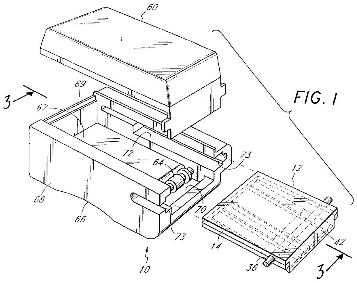
The present invention uses a minimal number of parts and dissipates a minimal amount of energy. The disposable concept which includes the cam followers and the pressure plate allows for a high precision pump without complicated assembly or loading mechanisms. The set loading and retaining channels allow precise positioning of the tubing, followers, and pressure plate without any adjustments or complicated, bulky, or expensive mechanisms. The disposable administration set results in an overall fluid delivery system which is small, lightweight, and ambulatory.
The design of the disposable administration set in combination with the plate referencing channels allows a sliding operation in order to load the set. This sliding operation allows for the transfer of information from the disposable administration set to the instrument from fixed sensors. These sensors may be optical, magnetic, or some other technology. The preferred embodiment uses optical sensors to read optically coded information from a label on the administration set. This capability permits the instrument to be programmed from the information included on the label. The instrument operator is thus free from programming tasks, which would be difficult in a clinical environment. Programming information can be added to the administration set during the preparation or prescription of the medication to be delivered. The unique sliding operation makes this programming simple and cost effective in the present invention.

Problems solved by technology

During the time that the downstream side finger completely squeezes the feeding tube, while the pumping portion of the tube is filling from an upstream supply, the flow of fluid to the patient is completely obstructed.
Completely obstructing the flow of medication for periods of time and providing pulsatile flow is often a clinically unsatisfactory and undesirable condition since a patient is deprived of medication for periods of time.
Additionally, fluid is delivered at non-uniform rates.
This may also result in an occluded tubing, so that the patient may be deprived of needed medication for several hours.
This solution is undesirable in view of the numerous parts involved.
Infusion devices utilizing piston valves and cylinders are also known to provide uniform flow; however, they do so at the expense of crude valving techniques and complex mechanisms.
The disposable diaphragms, however, are flimsy and thus require a very complex loading mechanism.
This has limited advantages, since the cam followers, which are not a part of the disposable assembly, are not renewed with each replacement.
Such an occlusion detection technique is undesirable in view of the complexities and cost involved.
These springs, of course, must be stiff enough to be unyielding as the cams squeeze the delivery tube.
These practices are not possible in a clinical environment.
The pump of the infusion device is non-functional when loaded with an alien disposable administration set.
Alien administration sets may have characteristics which are not suitable for safe operation of the fluid delivery system, and may operate outside of specified tolerance limits.
The pump will not operate with a standard piece of delivery tube, because it requires an administration set with cam followers and a pressure plate.

Method used


Image

  • Infusion device with disposable elements
  • Infusion device with disposable elements
  • Infusion device with disposable elements

Examples


Embodiment Construction

FIG. 1 illustrates the infusion device 10 of the preferred embodiment of the present invention for administering intravenous fluid at a consistent and uniform rate. The infusion device 10 is designed to be small, lightweight and ambulatory. The infusion device 10 includes a disposable administration set 12 having a plurality of cam followers 42 which are displaced in a predetermined sequence when depressed by a pumping mechanism 64 to squeeze a delivery tube 36 for dispensing fluid. The pumping mechanism 64 is driven by a commercially available motor 11 (not shown). Mounted within a housing structure 66, the disposable administration set 12 loads easily into the housing structure 66. Oriented directly above the housing structure 66 is an optional fluid reservoir 60 which provides a continuous flow of fluid to the inlet of the delivery tube 36 for dispensing and infusing fluid into a patient's body. Alternatively, the fluid delivery tube 36 may connect to an external reservoir (not s...


PUM


Abstract

An infusion device with a disposable administration set which is inexpensive to manufacture. In the preferred embodiment of the present invention the disposable administration set has a plurality of elongated cam followers connected to a plate assembly, wherein the cam followers are displaced in a predetermined sequence and forced against a delivery tube by cam means driven by rotary drive means. The disposable administration set is injection molded as a single integral piece. The disposable administration set includes adjustment spacers disposed between the plate assembly and the cam followers which adjust the distance between them to keep the device accurate. In the preferred embodiment of the present invention the cam assembly is configured to provide fluid delivery at a consistent and uniform rate. The device may also incude a pressure sensing pin positioned on the cam assembly which contacts the tubing during the pumping cycle. The drive current is sampled and processed at predetermined phases during the cam rotation cycle to detect the presence of an occlusion in the tubing.

Description

1. Field of the InventionThis invention relates generally to a medication infusion device for administering fluid to patients and more particularly to an improved, ambulatory infusion device with a disposable administration set which is inexpensive to manufacture, convenient to operate and which ensures fluid delivery at a consistent and uniform rate.2. Description of the Prior ArtAs a result of the ongoing need for improved health care, there is a continuous effort with regard to administering intravenous fluid to patients. As is well known, medication dispensers and infusion devices are used for infusion of predetermined amounts of medication into the body of a patient. Various types of medication dispensers employing different techniques for a variety of applications are known to exist. Some existing infusion devices utilize a series of diaphragms which roll up and down inside cylinders in response to pistons located within the cylinders. Such devices, for example, as disclosed i...

Claims


Application Information

Patent Timeline
Patent Type & Authority Patents(United States)
IPC IPC(8): A61M5/168A61M5/142F04B49/06F04B43/00F04B43/08
CPCF04B43/08F04B43/082F04B49/065A61M5/142A61M5/16831A61M5/16854A61M2205/6072A61M2205/6018F04B2203/0207
Inventor DAVIS, DAVID L.HATCH, RICHARD F.POIRIER, DAVID A.
Owner CARDINAL HEALTH INC
Why Eureka
Try Eureka