Minimally invasive bone broach

a bone broach and minimal technology, applied in the field of minimally invasive bone broaches, can solve the problems of inability to create a precise triangular cavity, incisions that may be undesired, and limitations of available bone broaches or rasps used for bone preparation, and achieve the effect of reducing the size of incisions

Active Publication Date: 2005-12-29
DEPUY PROD INC
View PDF25 Cites 116 Cited by
  • Summary
  • Abstract
  • Description
  • Claims
  • Application Information

AI Technical Summary

Benefits of technology

[0002] For implantation of prosthetic stems, such as hip stems, accurate preparation of the bone or intramedullary canal is important in order to guarantee good contact between the prosthesis stem and sleeve and the bone. The underlying concept behind precise preparation is that a precise bone envelope reduces the gaps between the stem and sleeve of the implant (i.e. prosthesis or prosthetic component) and the bone, thereby improving the initial and long-term bone ingrowth / fixation. The bone canal is presently prepared for implantation of a prosthetic stem by drilling and reaming a resected end of a bone, such as a femur, and then preparing an area adjacent the drilled hole to provide a seat for the prosthetic stem or a proximal sleeve coupled to the stem of a modular prosthetic system. A sleeve of modular prosthesis system is disclosed in U.S. Pat. No. 5,540,694, the disclosure of which is incorporated herein by this reference.
[0009] Since the oscillating saw used for neck resection and the straight reamers and conical reamers used for canal preparation are typically smaller than the instrument used for calcar preparation, the calcar preparation instrument often dictates the size of the incision required to perform the operation. When a patient undergoes total hip replacement (THR) it is common for the patient to stay in the hospital for one to two weeks. Rehabilitation therapy lasts months and many patients do not fully recover for years. Some patients never fully recover. This recovery process poses a substantial psychological and financial strain on THR patients. Many patients are in the latter years of their lives and this recovery period represents a significant portion of the remaining years. Current trends in joint replacement surgery suggest that smaller incision size can lead to faster recovery, improved quadriceps function and increased patient satisfaction.
[0015] The disclosed broaching system is configured to reduce the size of incision required for preparation of a bone to receive a prosthetic stem therein.

Problems solved by technology

Currently available broaches or rasps used for bone preparation have limitations.
Currently available broaches and rasps suffer from a tendency to be deflected by harder sections of bone so that they do not create a precise triangular cavity for receipt of the stem or sleeve of the prosthesis.
A limitation of milling systems today is that they are typically formed so that the drive shaft extends at an angle relative to the remainder of the frame from the end of the miller cutter machining the bone.
However, to accommodate any miller, it is necessary to make an incision which may be undesirably large for cosmetic or other reasons.
Rehabilitation therapy lasts months and many patients do not fully recover for years.
Some patients never fully recover.
This recovery process poses a substantial psychological and financial strain on THR patients.

Method used


Image

  • Minimally invasive bone broach
  • Minimally invasive bone broach
  • Minimally invasive bone broach

Examples


Embodiment Construction

[0030] For the purposes of promoting an understanding of the principles of the invention, reference will now be made to the embodiments illustrated in the drawings and described in the following written specification. It is understood that no limitation to the scope of the invention is thereby intended. It is further understood that the present invention includes any alterations and modifications to the illustrated embodiments and includes further applications of the principles of the invention as would normally occur to one skilled in the art to which this invention pertains.

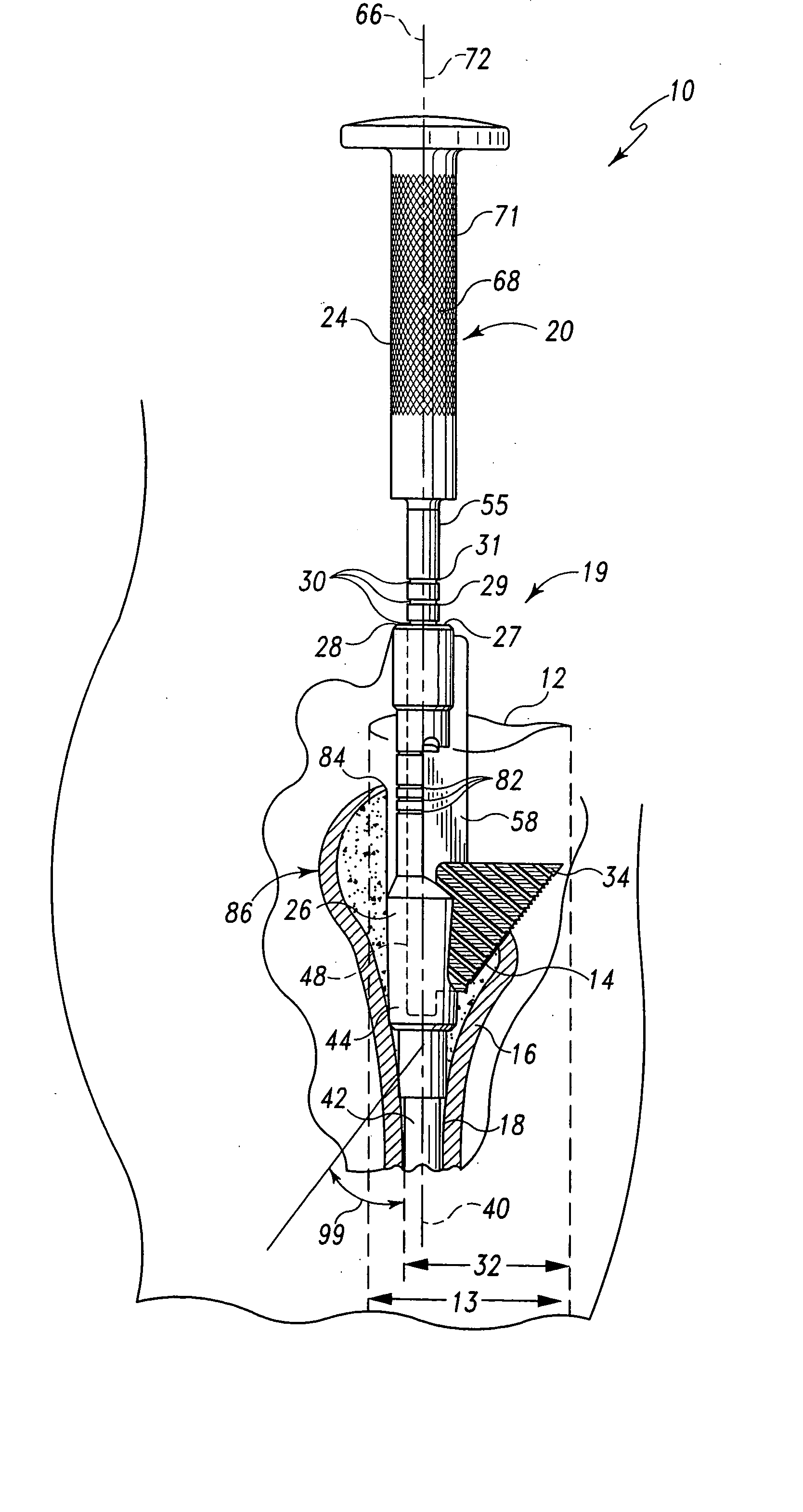
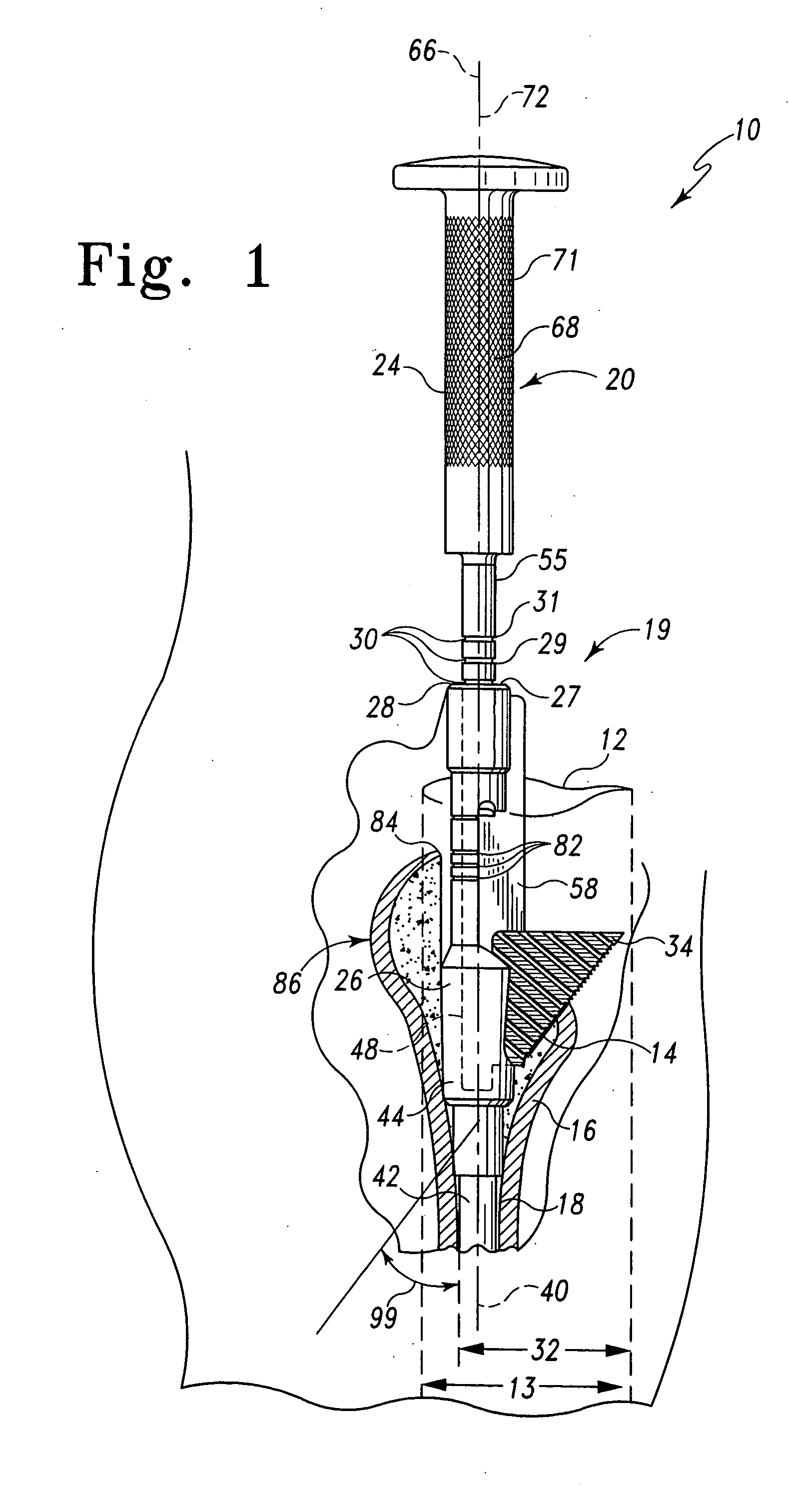
[0031] The disclosed broaching system 10 allows a surgeon to prepare bone for receipt of an implant through a smaller incision 12 compared to existing surgical instruments. In the illustrated embodiment, the incision 12 has a width 13. Illustratively, the disclosed broaching system 10 can be utilized with an incision having a width 13 of less than two and a half inches. In one preferred embodiment, the width 1...


PUM


Abstract

A broaching system is disclosed for creating a cavity in a bone. The cavity has a cross section which has a generally triangular profile having a first side generally parallel with an axis of the bone and a second side forming an acute angle with the first side. The cavity is contiguous with a pre-existing conical cavity in the bone. The apparatus comprises as shaft and a broach. The shaft has a longitudinal axis. The broach is mounted to the shaft and has a first cutting side mounted at the acute angle relative to the longitudinal axis of the shaft. The first cutting side is formed to include teeth. The shaft and broach are configured so that when the longitudinal axis of the shaft is advanced into the bone along the axis of the bone, the teeth of the broach form the triangular cavity. A method for cutting a triangular cavity in bone is also described. The method comprises a providing a shaft step, an incising step and a cutting step. The provided shaft is configured to be movable relative to the bone to be prepared and includes a broach coupled thereto to dispose a cutting surface of the broach at an acute angle relative to the shaft. The shaft and broach have a width defined by the distance between the shaft and the outer most portion of the cutting surface. The incising step includes incising the patient adjacent the bone to be prepared to form an incision having a length approximating the width of shaft and broach. The cutting step includes cutting the cavity by driving the broach by moving the shaft relative to the bone.

Description

BACKGROUND AND SUMMARY [0001] This invention relates to the field of artificial joint prostheses and, in particular, to an improved instrument for broaching a cavity in bone for receiving a prosthesis. [0002] For implantation of prosthetic stems, such as hip stems, accurate preparation of the bone or intramedullary canal is important in order to guarantee good contact between the prosthesis stem and sleeve and the bone. The underlying concept behind precise preparation is that a precise bone envelope reduces the gaps between the stem and sleeve of the implant (i.e. prosthesis or prosthetic component) and the bone, thereby improving the initial and long-term bone ingrowth / fixation. The bone canal is presently prepared for implantation of a prosthetic stem by drilling and reaming a resected end of a bone, such as a femur, and then preparing an area adjacent the drilled hole to provide a seat for the prosthetic stem or a proximal sleeve coupled to the stem of a modular prosthetic syste...

Claims


Application Information

Patent Timeline
Patent Type & Authority Applications(United States)
IPC IPC(8): A61B17/00A61B17/16A61B17/17A61F2/46
CPCA61B17/1659A61F2002/4658A61B17/175A61B17/1668
Inventor SCHNIEDERS, BARRYJONES, MICHAEL C.DANIELS, DAVID W.
Owner DEPUY PROD INC
Why Eureka
Try Eureka