Antenna assembly and method for manufacturing same
Active Publication Date: 2015-03-19
SCRAMOGE TECH LTD
View PDF4 Cites 68 Cited by
Summary
Abstract
Description
Claims
Application Information
AI Technical Summary
This helps you quickly interpret patents by identifying the three key elements:
Problems solved by technology
Method used
Benefits of technology
Benefits of technology
The patent describes a new antenna design that improves performance and simplifies fabrication. The design includes a magnetic substrate that is spaced apart from a coil part using a bonding layer, which enhances antenna performance. The coil part is directly placed on a non-magnetic insulating substrate, reducing the complexity of the fabrication process. The antenna pattern is connected to a connector through a conductive bridge, further simplifying the assembly. The antenna pattern is folded and connected to the connector, as well as formed simultaneously with a wireless charge and communication antenna pattern, improving power transmission efficiency and communication with external devices. Overall, the design allows for improved performance and simplified fabrication of the antenna.
Problems solved by technology
Although the electromagnetic induction technology has been rapidly commercialized while focusing on small-size devices, the power transmission distance thereof is short.
However, a typical antenna assembly embedded in a terminal has a thin thickness and the manufacturing process of the antenna assembly is complicated.
Method used
Image
Click on the blue label to locate the original text in one second.
Reading with bidirectional positioning of images and text.
Examples
first embodiment
[0375]In order to obtain an antenna pattern representing performance superior to that of the first embodiment shown in table 2, at least one of conditions shown in following equation 3 may be satisfied. In Equation 3, |a−b| represents the difference between a and b.
D1 / (|Lu1−Lb1| / 2)>2.248→D1 / |Lu1−Lb1|>1.124
D1 / (|Lmax−Lc1| / 2)>2.565→D1 / |Lmax−Lc1|>1.283
D1 / (|Lmin−Lc1| / 2)>18.19→D1 / |Lmin−Lc1|>9.095
90 degree≦max(A1,A2,A3,A4)<114 degree
66 degreeA1,A2,A3,A4)≦90 degree [Equation 3]
second embodiment
[0376]In order to obtain an antenna pattern representing performance superior to that of the second embodiment shown in table 2, at least one of conditions shown in Equation 4 may be satisfied.
[0377]In order to obtain an antenna pattern representing performance superior to the intermediate performance of the performance of the first embodiment and the performance of the second embodiment shown in table 2, at least one of conditions shown in following Equation 5 may be satisfied.
D1 / (|Lu1−Lb1| / 2)>3.75→D1 / |Lu1−Lb1|>1.875
D1 / (|Lmax−Lc1| / 2)>4.14→D1 / |Lmax−Lc1|>2.07
D1 / (|Lmin−Lc1| / 2)>14.359→D1 / |Lmin−Lc1|>7.18
90 degree≦max(A1,A2,A3,A4)<105 degree
75 degreeA1,A2,A3,A4)≦90 degree [Equation 5]
[0378]Referring to FIG. 49 again, the mask 83 is removed (step S109), and the inner antenna 200 and t...
PUM
Abstract
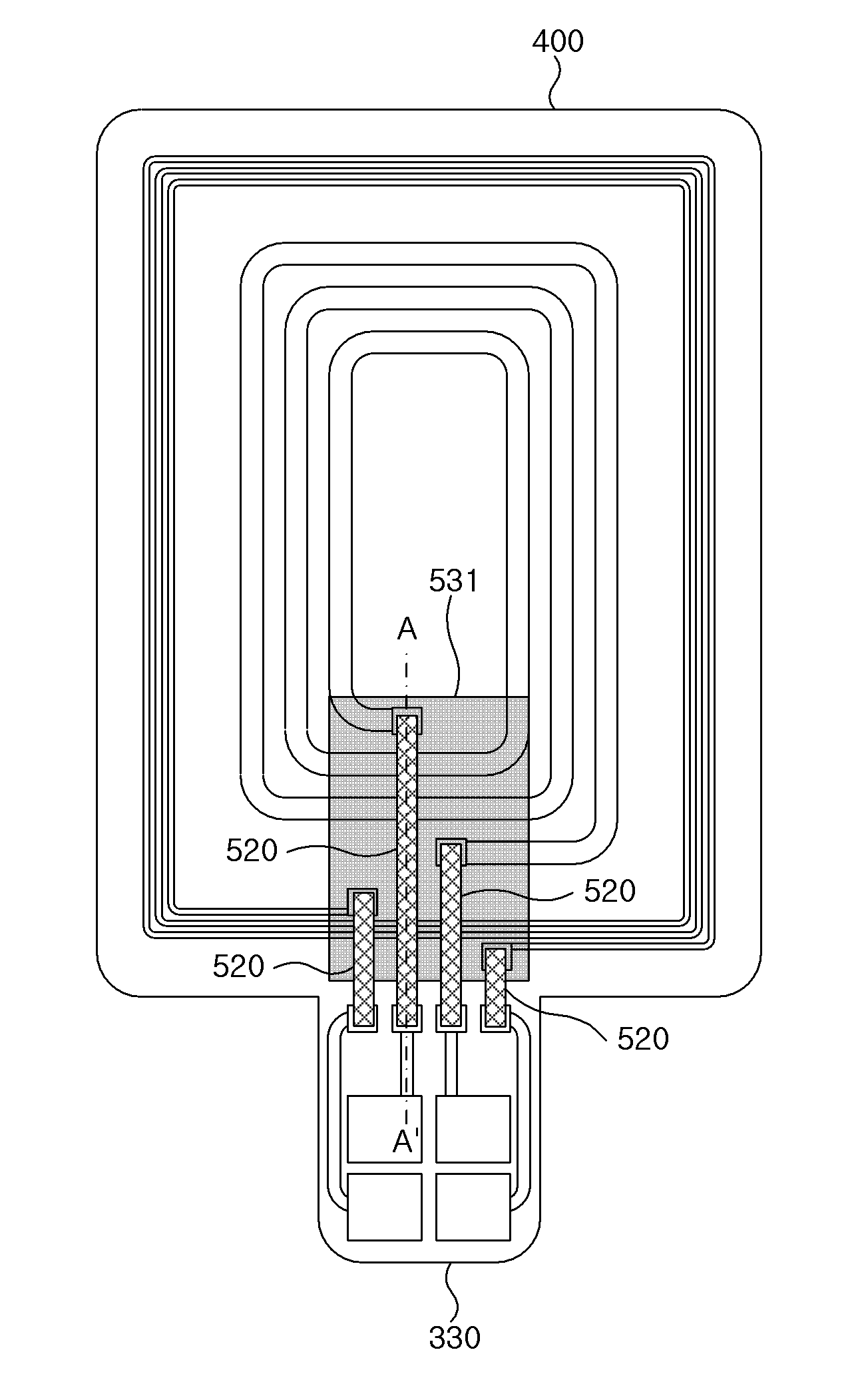
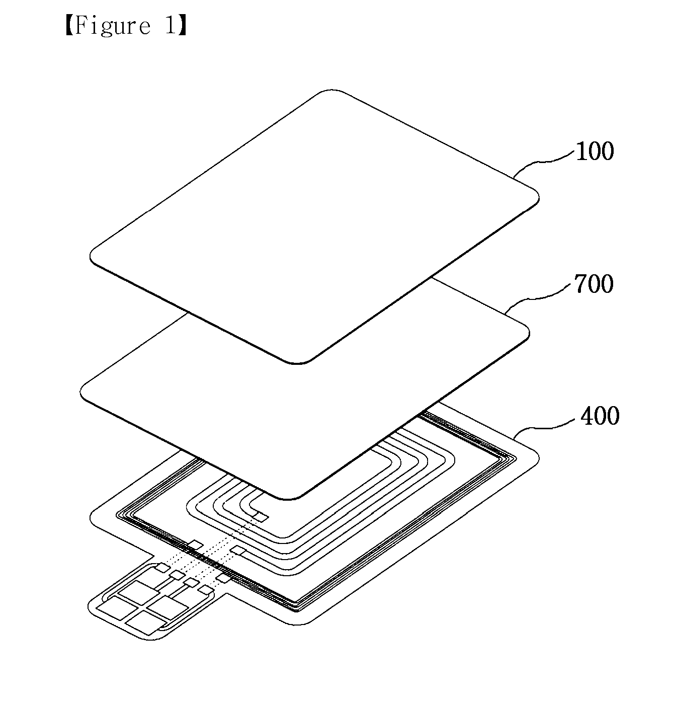
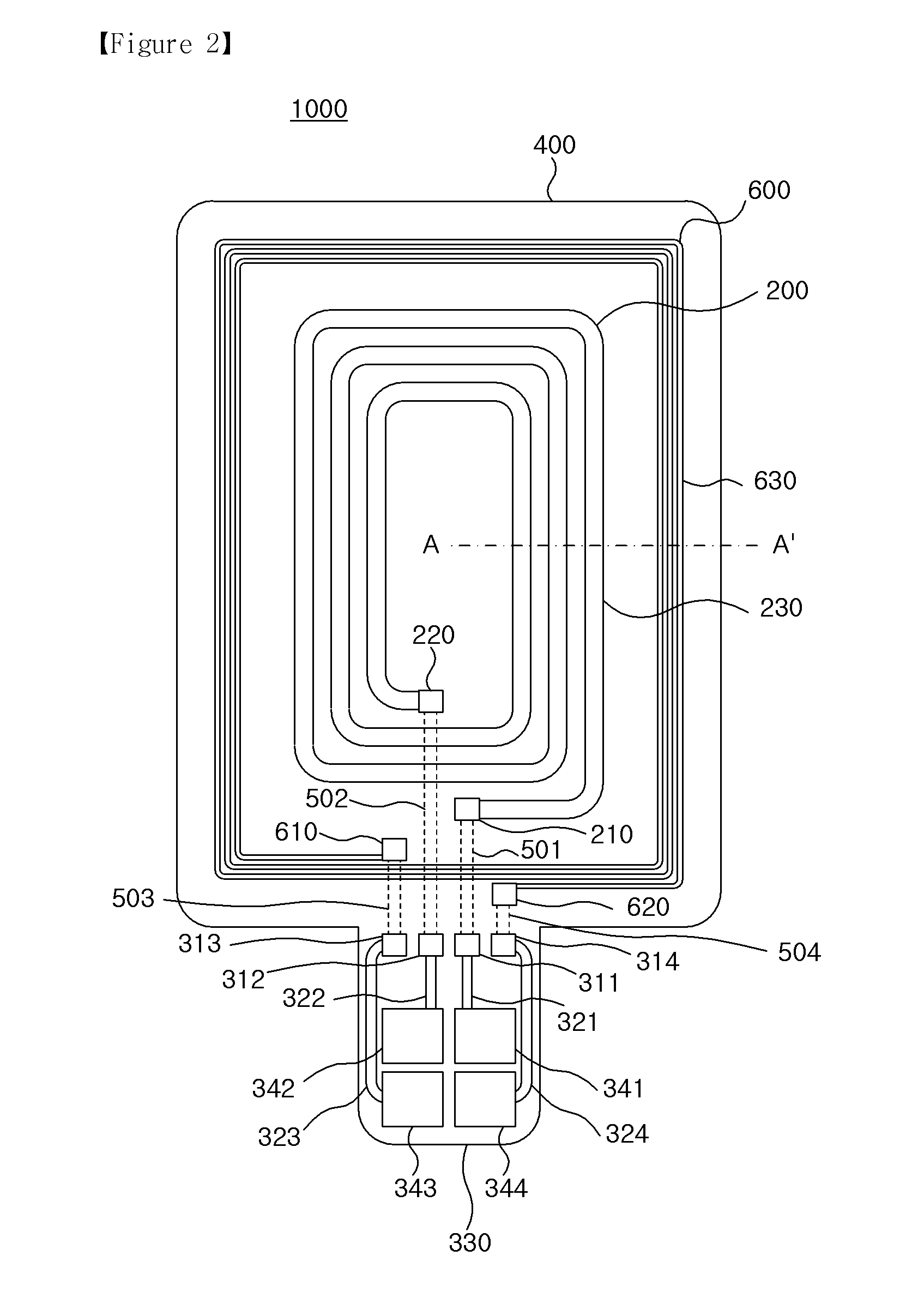
Disclosed is an antenna assembly including a substrate, and a wireless charge antenna pattern on the substrate. The wireless charge antenna pattern has a sectional surface including a plurality of inner angles in which two inner angles are different from each other. The antenna assembly includes a wireless communication antenna pattern formed on the substrate and provided at an outside of the wireless charge antenna pattern. The wireless communication antenna pattern has a plurality of inner angles at a sectional surface thereof, and a plurality of angle values of the inner angles provided at the sectional surface of the wireless communication antenna pattern correspond to a plurality of angle values of the inner angles provided at the sectional surface of the wireless charge antenna pattern, respectively.
Description
TECHNICAL FIELD[0001]The disclosure relates to an antenna assembly and a method of manufacturing the same. More particularly, the disclosure relates to an antenna assembly including an antenna, which is wirelessly rechargeable, and a method of manufacturing the same.BACKGROUND ART[0002]A wireless power transmission or a wireless energy transfer refers to a technology of wirelessly transferring electric energy to desired devices. In the 1800's, an electric motor or a transformer employing the principle of electromagnetic induction has been used and thereafter attempts have been performed to transmit electrical energy by irradiating electromagnetic waves, such as radio waves or lasers. Actually, electrical toothbrushes or electrical razors, which are frequently used in daily life, are charged based on the principle of electromagnetic induction. The electromagnetic induction refers to a phenomenon in which a voltage is induced so that a current flows when a magnetic field is varied aro...
Claims
Application Information
Patent Timeline
Application Date:The date an application was filed.
Publication Date:The date a patent or application was officially published.
First Publication Date:The earliest publication date of a patent with the same application number.
Issue Date:Publication date of the patent grant document.
PCT Entry Date:The Entry date of PCT National Phase.
Estimated Expiry Date:The statutory expiry date of a patent right according to the Patent Law, and it is the longest term of protection that the patent right can achieve without the termination of the patent right due to other reasons(Term extension factor has been taken into account ).
Invalid Date:Actual expiry date is based on effective date or publication date of legal transaction data of invalid patent.

