Short circuit fault current limiter

A technology of short-circuit fault and current limiter, which is applied in the direction of circuit devices, emergency protection circuit devices, overcurrent protection, etc., can solve the problems that the current limiting resistor technology is difficult to realize, and achieve heat dissipation design and avoid impact , to achieve the effect of high voltage current limiting

Inactive Publication Date: 2009-08-12
INST OF ELECTRICAL ENG CHINESE ACAD OF SCI
View PDF6 Cites 0 Cited by
  • Summary
  • Abstract
  • Description
  • Claims
  • Application Information

AI Technical Summary

Problems solved by technology

However, as the short-circuit fault capacity of the power grid increases, the current-limiting resistance of the current limiter is technically difficult to realize

Method used


Image

  • Short circuit fault current limiter
  • Short circuit fault current limiter
  • Short circuit fault current limiter

Examples


Embodiment Construction

[0024] The present invention will be further described below in conjunction with accompanying drawing and specific embodiment:

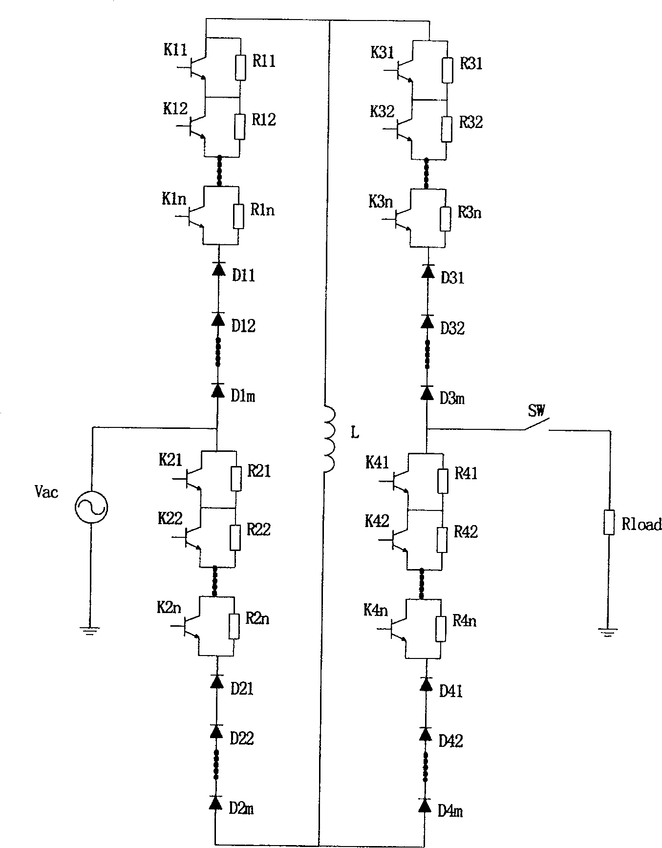
[0025] like figure 2 As shown, Embodiment 1 of the present invention is a single-phase short-circuit fault current limiter. The 1st-1st controllable solid-state switch tube K11, the 1st-2nd controllable solid-state switch tube K12, ..., the 1-Nth controllable solid-state switch tube K1n are respectively connected with the 1-1st current limiting resistor R11, the 1st-2nd controllable solid-state switch tube K1n Current limiting resistors R12, ..., 1-N current limiting resistors R1n are connected in parallel, and then connected in series with 1-1 diode D11, 1-2 diode D12, ..., 1-M diode D1m in series, 2- 1 Controllable solid-state switch tube K21, 2-2nd controllable solid-state switch tube K22, ..., 2-N controllable solid-state switch tube K2n respectively connected with 2-1st current-limiting resistor R21, 2-2nd current-limiting resistor R22, ..., t...


PUM


Abstract

A short trouble current limiter in particular relates to transmission and distribution network failure current limiter. It features on available bridge circuit type short trouble current limiter basic, rectifying bridge arm consisting of controllable solid-state switch tube series connected with current limiting resistance shunt circuit and then series connected with diode. The present invention realizes inductor and resistor combined current limiting, not only limiting failure current peak value but also steady state value.

Description

technical field [0001] The invention relates to a short-circuit fault current limiter, in particular to a fault current limiter for transmission and distribution networks. Background technique [0002] With the rapid development of the national economy, the society's demand for electricity continues to increase, which drives the continuous development of the power system. The capacity of single machines and power plants, the capacity of substations, and the load of cities and industrial centers continue to increase, which makes the interconnection of power systems , the level of short-circuit current in the power grid at all levels is increasing continuously, and the destructiveness of short-circuit faults to the power system and its connected electrical equipment is also increasing. Moreover, while the demand for electric energy is increasing day by day, people also put forward higher requirements for power quality, power supply reliability and security. However, the trans...

Claims


Application Information

Patent Timeline
Patent Type & Authority Patents(China)
IPC IPC(8): H02H9/02H02H3/08
Inventor 肖立业张志丰赵彩宏
Owner INST OF ELECTRICAL ENG CHINESE ACAD OF SCI
Why Eureka
Try Eureka