Ceramic filter flow-limiting valve gate

A ceramic filter and valve technology, applied in valve details, valve devices, mechanical equipment, etc., can solve the problems of loosening, the flow-limiting valve does not have a positioning function, etc., and achieve the effect of improving the flow-limiting effect.

Inactive Publication Date: 2015-05-13
胡俊
View PDF4 Cites 2 Cited by
  • Summary
  • Abstract
  • Description
  • Claims
  • Application Information

AI Technical Summary

Problems solved by technology

However, the flow-limiting valve of the ceramic filter commonly used at present does no

Method used


Image

  • Ceramic filter flow-limiting valve gate
  • Ceramic filter flow-limiting valve gate

Examples


Embodiment Construction

[0012] The preferred embodiments of the present invention will be described in detail below in conjunction with the accompanying drawings, so that the advantages and features of the present invention can be more easily understood by those skilled in the art, so as to define the protection scope of the present invention more clearly.

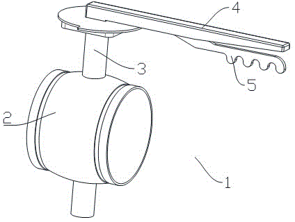
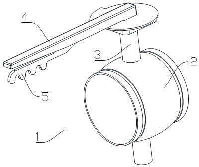
[0013] The invention provides a ceramic filter flow limiting valve which is not easy to loose.

[0014] Such as figure 1 , figure 2 As shown, a flow limiting valve 1 for a ceramic filter includes a pipe connecting portion 2, a control shaft 3 is rotatably provided on the pipe connecting portion 2, and a control shaft 3 is provided on the control shaft 3. The operating handle 4 is provided with a positioning control rod 5 at the bottom of the operating handle 4 .

[0015] Such as figure 1 , figure 2 As shown, the surface of the operating handle 4 is provided with anti-slip threads.

[0016] Such as figure 1 , figure 2 As shown, a certai...


PUM


Abstract

The invention discloses a ceramic filter flow-limiting valve gate. The ceramic filter flow-limiting valve gate comprises a tube body interconnecting piece, the tube body interconnecting piece is rotatably provided with a control shaft, the control shaft is provided with an operating handle, the bottom of the operating handle is provided with a positioning control rod, an anti-skid whorl is arranged on the surface of the operating handle, and the positioning control rod and the operating handle keep a certain included angle. Due to the operating handle of the valve gate of the ceramic filter flow-limiting valve gate is provided with a control rod used for preventing the operating handle from loosening, and the nonoccurrence of the displacement of a valve gate handle is guaranteed even under a condition of violent vibration of a machine. Accordingly, the flow-limiting effect of the ceramic filter flow-limiting valve gate is greatly improved.

Description

technical field [0001] The invention relates to a valve, more precisely, a flow-limiting valve for a ceramic filter. Background technique [0002] Ceramic filter is a kind of industrial equipment that is widely used in industrial production, with high work efficiency and great applicability. However, the flow-limiting valve of the ceramic filter commonly used at present does not have a positioning function, and is easily affected by the machine and becomes loose. Contents of the invention [0003] The invention mainly solves the technical problems existing in the prior art, thereby providing a ceramic filter flow-limiting valve that is not easy to loosen. [0004] Above-mentioned technical problem of the present invention is mainly solved by following technical scheme: [0005] A flow-limiting valve for a ceramic filter, comprising a pipe body connection part, a control shaft is rotatably provided on the pipe body connection part, and an operating handle is provided on t...

Claims


Application Information

Patent Timeline
IPC IPC(8): F16K35/00F16K31/60
CPCF16K35/00F16K31/60
Inventor 胡俊
Owner 胡俊
Why Eureka
Try Eureka