Winding device

A technology of winding device and sensing device, which is applied in the direction of transportation and packaging, thin material handling, and delivery of filamentous materials, etc. It can solve problems such as cable breakage, achieve the effect of avoiding bending load and being less susceptible to interference

Inactive Publication Date: 2007-08-22
SAURER GMBH & CO KG
View PDF2 Cites 4 Cited by
  • Summary
  • Abstract
  • Description
  • Claims
  • Application Information

AI Technical Summary

Problems solved by technology

In principle, however, there is the risk of cable breakage or undesired bending stresses occurring at the connecting point between the Hall sensor and the connecting lead during a permanent movement of the connecting lead.

Method used


Image

  • Winding device
  • Winding device
  • Winding device

Examples


Embodiment Construction

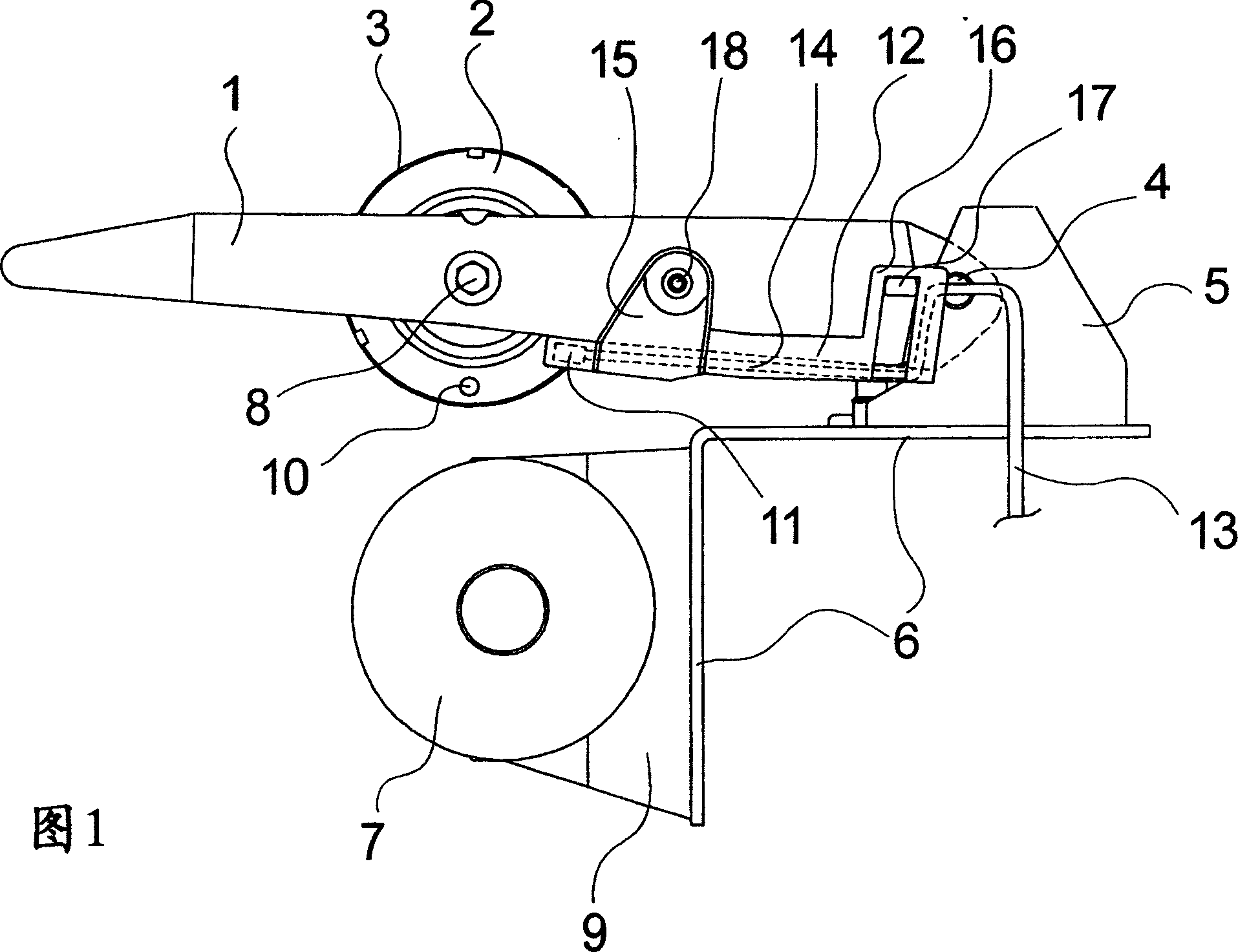
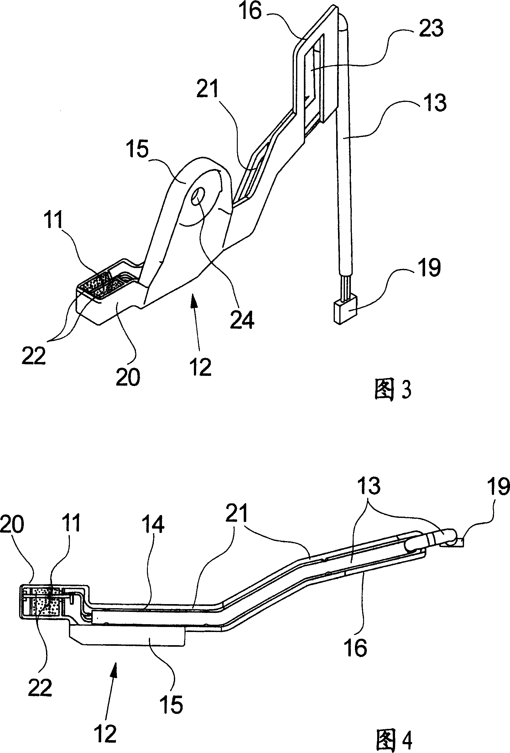
[0022] A first embodiment of the winding device according to the invention is depicted in FIGS. 1 and 2 . Figure 1 shows a side view of the embodiment, while Figure 2 shows a partial front view of the winding device. The following description applies to both figures, as long as it is not clear which one of the figures it refers to.

[0023] The view of the winding device according to the invention only shows the components which are relevant for the invention. Such a winding device is known from EP 0 921 087 B1, to which reference is hereby expressly made for the explanation of the overall structure and for the explanation of the function and only the components which are essential for the invention are explained below.

[0024] This exemplary embodiment of the winding device according to the invention has a double-armed bobbin holder 1 with two tensioning disks 2 arranged opposite each other. Each tensioning disk 2 is connected to the bobbin holder via a disk shaft 8 on whi...


PUM


Abstract

The invention relates to a winding device for winding yarns on a bobbin and comprising a double-arm type bobbin frame. The bobbin frame is provided with two tensioning disks which are rotatablely supported relatively, and between which a bobbin of yarns to be winded to a spindle is arranged. The bobbin or spindle is drived by a driven roller, the bobbin is held around the driven roller when being winded. A sensor device is provided for detecting rotate speed setting of the bobbin, the sensor device includes a magnet and a Hall sensor, wherein the magnet is arranged on one tensioning disk, and the Hall sensor is arranged on the bobbin frame and connected with at least a connection wire. In order to ensure a high functional characteristic and a replaceable characteristic of an electronic apparatus component, the Hall sensor of the invention is held by a separated sensor support which is detachablely connected with the bobbin frame and has a cable passage for receiving the connection wires connecting with the Hall sensor.

Description

technical field [0001] The invention relates to a winding device for winding a yarn onto a bobbin according to the preamble of claim 1 . Background technique [0002] A similar winding device is known from EP 0 648 701 A1. [0003] The known winding device has a bobbin holder which holds a rotatably mounted tensioning disc at two opposite ends. A bobbin for receiving a yarn to be wound into a bobbin is tensioned between the tensioning discs. The bobbin holder is held rotatably on the opposite end of the swivel shaft, where the bobbin or bobbin to be wound rests against the circumference of a driven roller. The driven roller is driven via a motor. In such a winding device, the movably held bobbin holder serves on the one hand to permit the enlargement of the bobbin despite permanent contact with the driven roller during yarn winding, and on the other Cartridge replacement is carried out in the open position. The bobbin holder to a certain extent performs a permanent move...

Claims


Application Information

Patent Timeline
IPC IPC(8): B65H54/02B65H63/00B65H54/54B65H54/70
Inventor 德特勒夫・奥伯斯特拉斯
Owner SAURER GMBH & CO KG
Why Eureka
Try Eureka