Arm stopper mechanism, and electric power-steering device using arm stopper mechanism

a technology of stopper mechanism and stopper arm, which is applied in the direction of mechanical equipment, transportation and packaging, cycles, etc., can solve the problems of sometimes becoming difficult to steer, and achieve the effect of inhibiting the bending load

Active Publication Date: 2017-06-20
HITACHI ASTEMO LTD
View PDF19 Cites 0 Cited by
  • Summary
  • Abstract
  • Description
  • Claims
  • Application Information

AI Technical Summary

Benefits of technology

[0028]The arm stopper mechanism configured as described above can cause the part (that is, the center position of the part which comes into contact with the abutting face of the pitman arm and the contact face of the stopper), to which the abutting load vector is applied, to approach the periphery of the tie rod role to which the input load vector is applied. Thus, the arm stopper mechanism configured as described above can efficiently inhibit vibrations.
[0032]With the arm stopper mechanism configured as described above, the abutting faces are respectively provided to side face portions of the pitman arm body. In addition, with the arm stopper mechanism configured as described above, the input load vector and the abutting load vector cancel each other. Thus, the arm stopper mechanism can inhibit the bending load that is applied to the output shaft.
[0036]With the arm stopper mechanism configured as described above, the abutting faces of the pitman arm are respectively provided to side face portions of a protruding part which protrudes upward near the center of a top face of the pitman arm body. In addition, with the arm stopper mechanism configured as described above, the input load vector and the abutting load vector cancel each other. Thus, the arm stopper mechanism configured as described above can inhibit the bending load that is applied to the output shaft. In addition, with the arm stopper mechanism configured as described above, since the pitman arm is configured such that the abutting face does not protrude in the turning direction, the pitman arm can be configured in a compact manner.
[0040]Since the electric power-steering device according to the second invention is provided with the arm stopper mechanism according to the first invention, it can inhibit the bending load that is applied to the output shaft.
[0041]According to the present invention, it is possible to inhibit the bending load that is applied to the output shaft.

Problems solved by technology

Nevertheless, with a related-art electric power-steering device, since a related-art arm stopper mechanism is not of a configuration which gives consideration to inhibiting the bending load that is applied to the output shaft as explained below, there is a problem in that the steering would sometimes become difficult.

Method used


Image

  • Arm stopper mechanism, and electric power-steering device using arm stopper mechanism
  • Arm stopper mechanism, and electric power-steering device using arm stopper mechanism
  • Arm stopper mechanism, and electric power-steering device using arm stopper mechanism

Examples


first embodiment

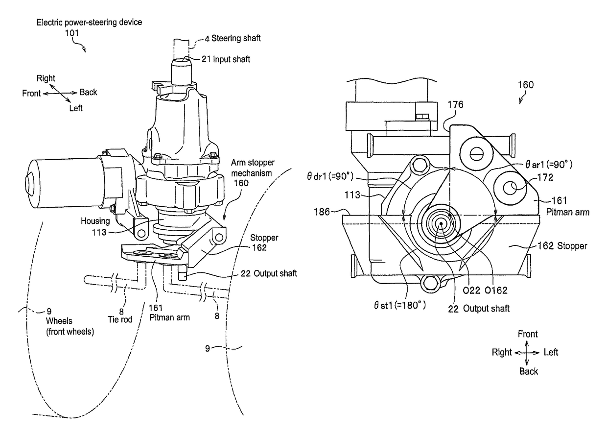
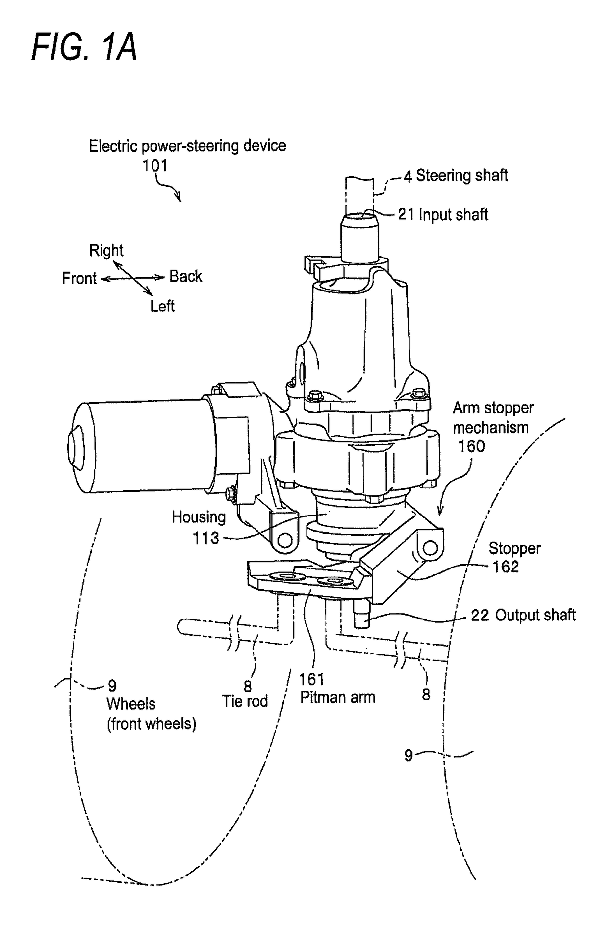
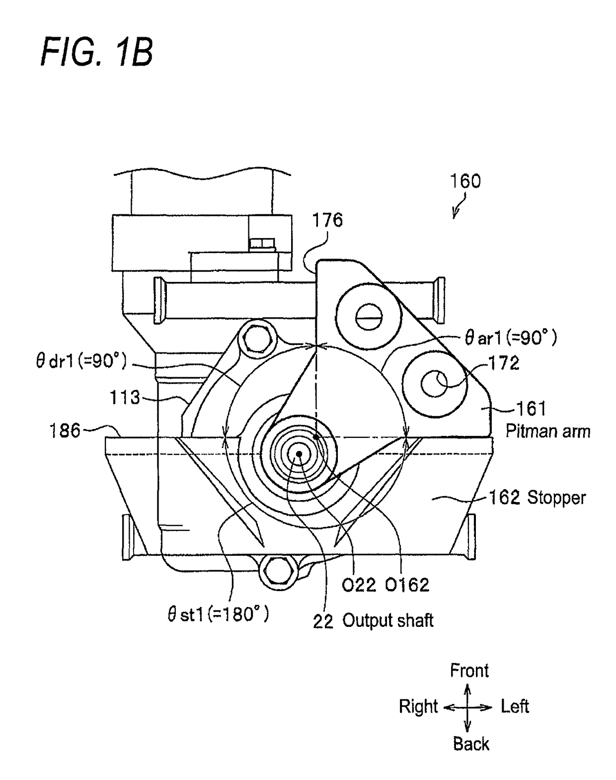
[0060]The configuration of the arm stopper mechanism 160 according to the first embodiment is now explained.

[0061]Here, in order to facilitate the understanding of the explanation of the features of the arm stopper mechanism 160 according to the first embodiment, the configuration of the arm stopper mechanism 60 according to the comparative example is foremost explained with reference to FIGS. 10A and 10B, and FIGS. 11A and 11B to FIGS. 12A and 12B, and the load vectors applied to the principal parts of the arm stopper mechanism 60 according to the comparative example are subsequently explained with reference to FIG. 13.

[0062]Thereafter, the relation of the input load vector and the abutting load vector, and the bending load vector is explained with reference to FIG. 13 and FIGS. 14A to 14C.

[0063]Furthermore thereafter, the configuration of the arm stopper mechanism 160 according to the first embodiment is explained with reference to FIGS. 1A and 1B, and FIGS. 2A and 2B to FIGS. 4A ...

second embodiment

[0153]The arm stopper mechanism 160 according to the first embodiment was configured such that the abutting face 176 is provided to the side face portion of the body of the pitman arm 161. The pitman arm 161 is configured such that the abutting part 174 is protruding to the outside (turning direction), on which the abutting face 176 is formed, in order to define the maximum steering angle of the steering wheel.

[0154]Meanwhile, in the second embodiment, provided is an arm stopper mechanism 260 that is configured such that the abutting part does not protrude to the outside.

[0155]

[0156]The configuration of the arm stopper mechanism 260 according to the second embodiment is now explained with reference to FIG. 6 to FIG. 8. FIG. 6 is a schematic configuration diagram of the arm stopper mechanism 260 according to the second embodiment viewed from a lower face direction. FIGS. 7A to 7C are schematic configuration diagrams of the pitman arm 261 of the arm stopper mechanism 260 according to ...


PUM


Abstract

An arm stopper mechanism, includes a pitman arm which includes an output shaft hole into which an output shaft is fitted, two tie rod holes onto which tie rods are respectively mounted, and two abutting faces to which a stopper is abutted; and the stopper which includes two contact faces, in which an angle formed by the two contact faces of the stopper is greater than an angle formed by the two abutting faces of the pitman arm and is 90° or more.

Description

CROSS-REFERENCE TO RELATED APPLICATIONS[0001]This application is based on and claims priority under 35 U.S.C. 119 from Japanese Patent Application No. 2013-070676 filed on Mar. 28, 2013, the entire content of which is incorporated herein by reference.BACKGROUND[0002]1. Technical Field[0003]The present invention relates to an arm stopper mechanism for inhibiting a turning angle of a pitman arm mounted with a tie rod, and an electric power-steering device using such an arm stopper mechanism.[0004]2. Related Art[0005]For example, with a saddle-ride type vehicle such as an all terrain vehicle (ATV), the electric power-steering device is interposed between a steering shaft on the side of the steering wheel and a steering member on the side of the wheels (front wheels). The electric power-steering device is a device which assists, by using the torque generated by an electric motor, the steering force applied by the driver to the steering wheel.[0006]The electric power-steering device inco...

Claims


Application Information

Patent Timeline
Patent Type & Authority Patents(United States)
IPC IPC(8): B62D3/02B62D5/04B62K5/08
CPCB62D3/02B62D5/0421B62K5/08Y10T74/18888
Inventor MURAKAMI, TAKUYAKUNO, SHINJI
Owner HITACHI ASTEMO LTD
Why Eureka
Try Eureka