
Touch screen display and method of operating the same

a touch screen and display technology, applied in the field of touch screen display and the same operation method, can solve the problems of relatively high drive voltage and relatively high power consumption

Active Publication Date: 2012-06-28
SAMSUNG ELECTRONICS CO LTD
View PDF3 Cites 73 Cited by
  • Summary
  • Abstract
  • Description
  • Claims
  • Application Information

AI Technical Summary

Benefits of technology

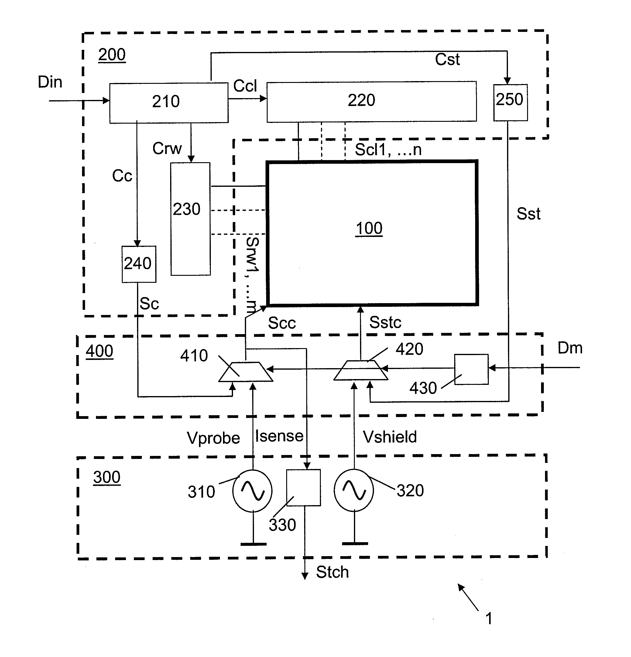
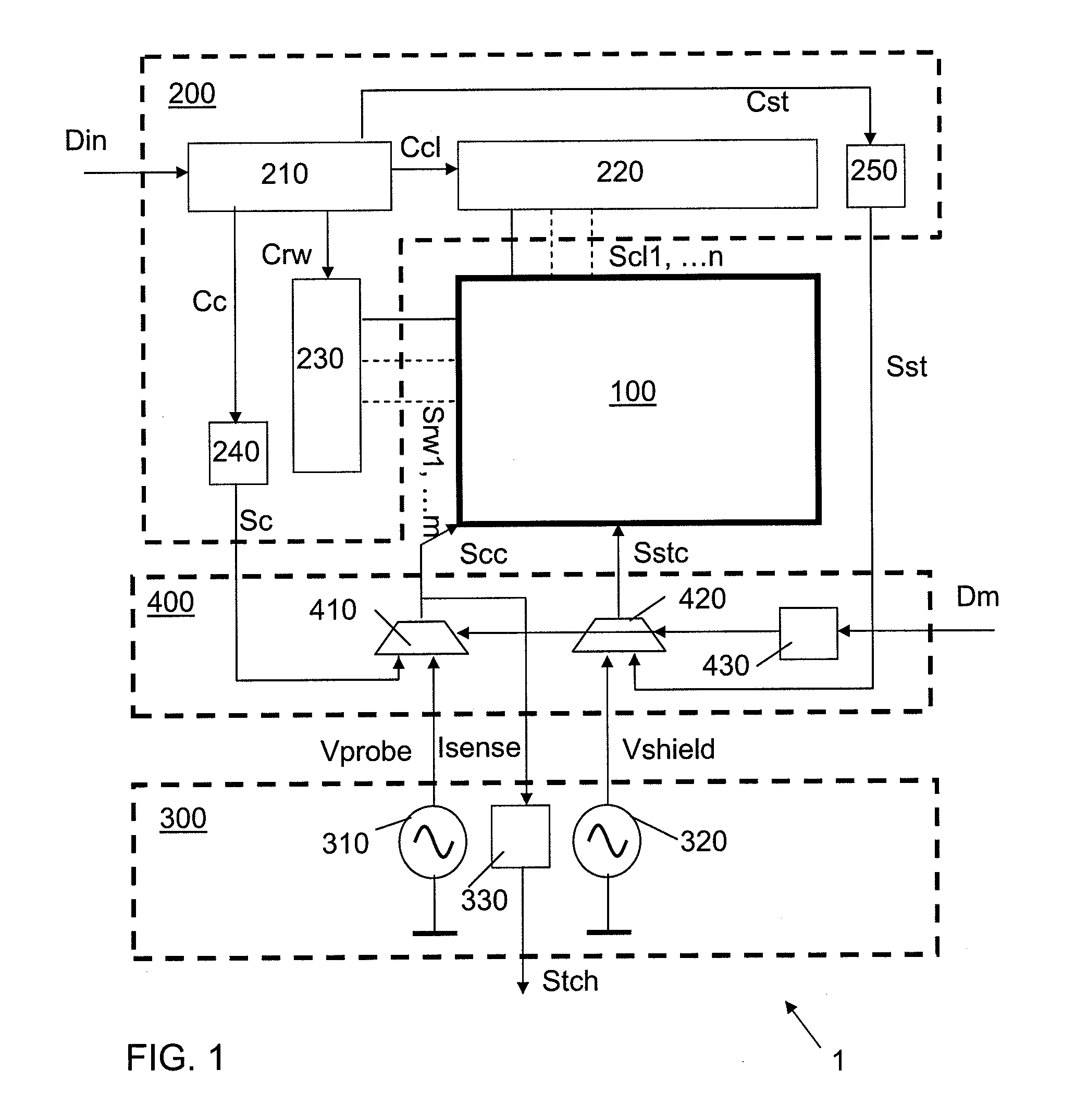
[0024]By the measures of the present invention a touch screen functionality with a relatively high sensitivity is achieved even with a relatively low amplitude of the driving voltage used for sensing. Without wishing to be bound by theory it is believed that the effect of the application of the shield signal to other electrically conductive structures in the display is a reduction of parasitic currents between the common electrode layer and said other electrically conductive structures. With this reduction noise in measured currents is reduced, so that the accuracy of a position determination can be improved without increasing a drive voltage.
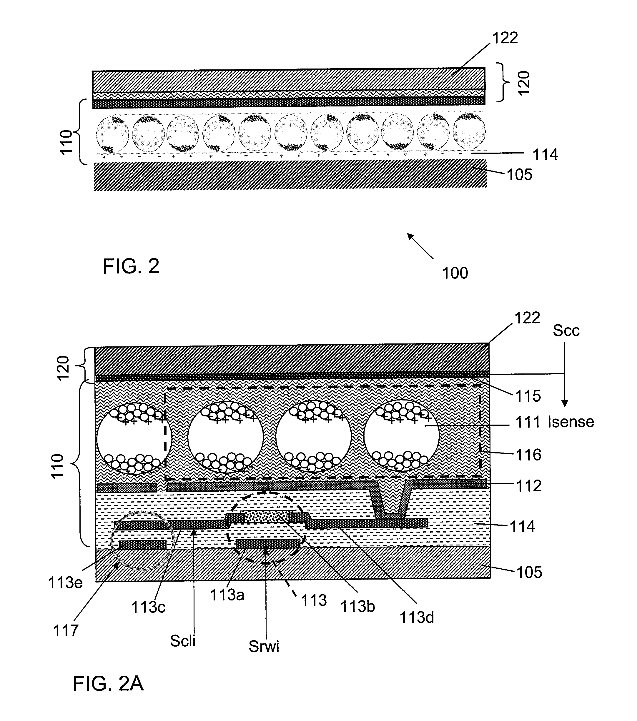
[0029]In an embodiment of the display device having an active matrix layer, the pixel electrodes are coupled to a first side of a respective storage capacitor, a second side of said storage capacitor being coupled to the storage line and the at least one of the control signals is a signal for driving the storage line. The storage line may be one of a plurality of storage lines, wherein each of the storage lines is coupled to the combination unit, which provides a storage line control signal obtained by a combination of the shield signal and an input storage line control signal. This embodiment wherein the shield signal, having the same phase and frequency as the probe signal, is provided to the storage lines either intermittently, or superposed to the input storage line control signal is particularly effective for suppressing noise in the sense signals. Additionally, or alternatively, the shield signal is coupled via the combination unit to other conductive structures of the display device such as, for example, a ground network.

Problems solved by technology

However, it has been found that a touch sensitive structure that shares the common electrode layer with the display structure requires relatively high drive voltages as compared to embodiments wherein the common electrode layer is not shared in order to achieve a sufficient sensitivity.
The requirement for relatively high driving voltages results in a relatively high power consumption.

Method used


Image

  • Touch screen display and method of operating the same
  • Touch screen display and method of operating the same
  • Touch screen display and method of operating the same

Examples


Embodiment Construction

[0047]In the following detailed description numerous specific details are set forth in order to provide a thorough understanding of the present invention. However, it will be understood by one skilled in the art that the present invention may be practiced without these specific details. In other instances, well known methods, procedures, and components have not been described in detail so as not to obscure aspects of the present invention.

[0048]Embodiments of the invention are described herein with reference to cross-section illustrations that are schematic illustrations of idealized embodiments (and intermediate structures) of the invention. As such, variations from the shapes of the illustrations as a result, for example, of manufacturing techniques and / or tolerances, are to be expected. Thus, embodiments of the invention should not be construed as limited to the particular shapes and sizes of regions illustrated herein but are to include deviations in shapes that result, for exam...


PUM


Abstract

A touch screen display device is described that includes a display panel, a display driver, a sensor circuit and a combination unit. The display panel has a plurality of display elements arranged between a first and a second electrode layer. The display driver is arranged for providing display signals comprising a common display signal and an input control signal to the display panel. The sensor circuit is arranged for providing a probe signal and a shield signal mutually having the same phase and frequency and for generating a touch signal in response to the output signal received from the first electrode layer. The combination unit provides a drive signal to the first electrode layer derived from the common display signal and the probe signal, and further provides an output control signal for the display panel from the input control signal and the shield signal.

Description

BACKGROUND OF THE INVENTION[0001]1. Field of the Invention[0002]The present invention relates to a display device with a touch sensor. The present invention further relates to a method of operating a display device with a touch sensor.[0003]2. Related Art[0004]WO 2009075577 discloses a display device comprising a flexible display panel that includes a display structure responsive to output signals from the data processing facility, and a capacitive touch sensitive structure. In an embodiment the display structure and the touch sensitive structure share a transparent common electrode layer that is alternately coupled to a display driver and to a touch screen driver via a switching element.[0005]During a first phase of operation the transparent common electrode layer, such as an ITO layer, is coupled to the display driver, so that the display driver can update the content of the display panel.[0006]During a second phase of operation the common electrode layer is coupled to the touch s...

Claims


Application Information

Patent Timeline
IPC IPC(8): G06F3/041
CPCG06F3/0412G06F3/044G06F3/0418G06F3/04184G06F3/0443
Inventor VAN LIESHOUT, PETRUS JOHANNES GERARDUSPEETERS, BART
Owner SAMSUNG ELECTRONICS CO LTD
Learn More