Roller press

A press and roller technology, applied in grain processing, etc., can solve problems such as broken tiles

Inactive Publication Date: 2021-01-15
MASCHFAB KOPPERN GMBH & CO KG
View PDF10 Cites 0 Cited by
  • Summary
  • Abstract
  • Description
  • Claims
  • Application Information

AI Technical Summary

Problems solved by technology

However, at high forces in particularly dangerous areas, fragmentation of individual parts of the tile-like element can occur, and this fragmentation in turn provides a point of action for its further fragmentation, so that a solution with a tile-like structure essentially requires continue to improve

Method used


Image

  • Roller press
  • Roller press
  • Roller press

Examples


Embodiment Construction
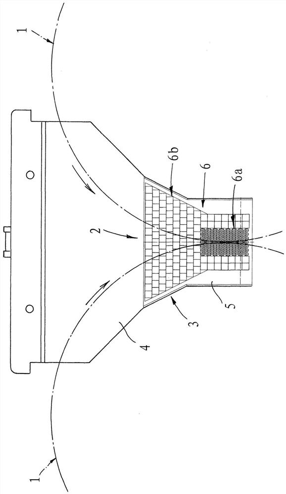
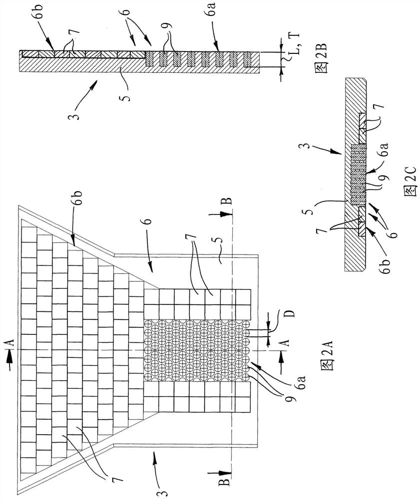
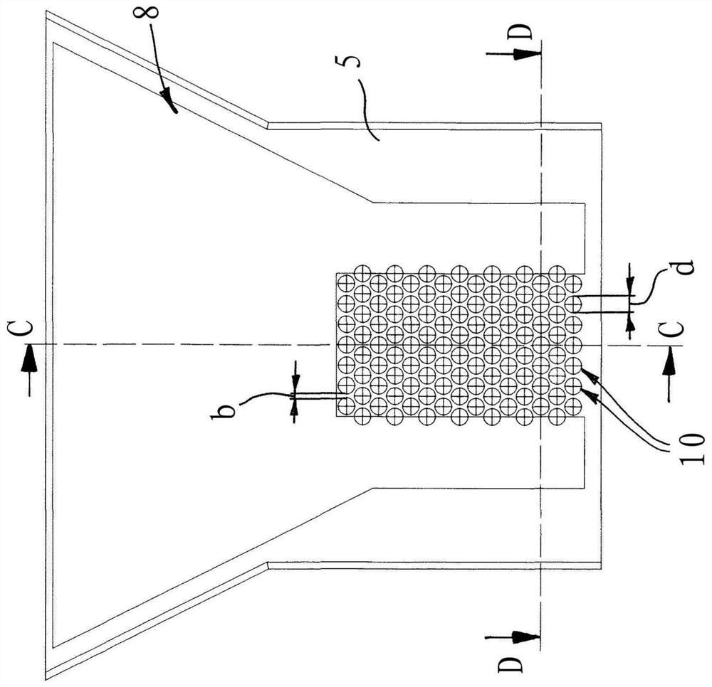
[0028]The material entry area of ​​a roller press is shown schematically and highly simplified in the figure. The roller press can be used, for example, for crushing materials and is also called a high-pressure roller press or a Gutbert roller mill. The roller press has two pressure rollers 1, which are supported in a machine frame, not shown, rotatably opposite to each other. The pressure roller 1 is only shown schematically. A roller gap 2 which is funnel-shaped in the direction of rotation of the rollers is formed between the pressure rollers 1. The material to be processed is introduced into the roller gap 2 from above, for example by gravity conveying or also by means of a screw feeder. The details are not shown here. The invention particularly relates to the side restraint plate 3, which is arranged beside the pressure roller 1 in such a roller press and thus restricts the roller gap 2 on the side of the roller end. infigure 1Only one of the restriction plates 3 is shown in, w...


PUM


Abstract

The invention relates to a roller press, more particularly for comminuting material, comprising two rotatably mounted pressing rollers (1), between which a roller gap (2) is formed, in which the material to be processed is guided, wherein: - the roller gap (2) is delimited at the roller end faces by means of delimiting plates (3); - the delimiting plates each have a base plate (5) and an anti-wearlayer (6) fastened to the base plate (5); - the anti-wear layer (6) is formed by individual anti-wear elements at least in a first wear zone (6a), which anti-wear elements consist of a wear-resistantmaterial having a greater hardness than the base plate (5). Said roller press is characterized in that the anti-wear elements are designed as pins (9) in the first wear zone (6a), that the base plate(5) has a plurality of individual holes (10) formed in the base plate (5) in the first wear zone (6a), and that a single pin (9) is inserted over the full length (L) thereof into each hole (10) in such a way that the pins (9) do not protrude from the holes (10).

Description

Technical field[0001]The present invention relates to a roller press having two rotatably supported pressure rollers, a roller gap is formed between the pressure rollers, and a material to be processed is introduced into the roller gap, wherein the roller The end side (or on the side) limits the roller gap by means of a limiting plate, wherein the limiting plate respectively has a base plate and a wear protection layer fixed on the base plate, wherein the wear protection layer is at least in the first wear zone (subject to high The load) is formed by individual wear protection elements, which are (at least partially) made of a wear-resistant material having a higher hardness relative to the substrate.Background technique[0002]Roller presses are especially used for crushing materials, especially very abrasive materials, such as ore, cement bricks, slag, kimberlite, coal or ceramic raw materials. This type of roller press used for high-pressure crushing is also called a Gutbert roller...

Claims


Application Information

Patent Timeline
Patent Type & Authority Applications(China)
IPC IPC(8): B02C4/28
CPCB02C4/283B02C2210/02B02C4/02B02C4/305
Inventor Z·A·加尔杜拉
Owner MASCHFAB KOPPERN GMBH & CO KG
Why Eureka
Try Eureka