Fuel filter of a motor vehicle

a technology of fuel filter and motor vehicle, which is applied in the direction of filtration separation, machines/engines, and separation processes, etc., can solve the problems of increasing the amount of engine compartment mounting space, high manufacturing costs, and relatively brittle components, so as to avoid local force and stress peaks, the effect of excellent ratio of employed materials

Inactive Publication Date: 2013-05-07
MANN HUMMEL GMBH
View PDF4 Cites 0 Cited by
  • Summary
  • Abstract
  • Description
  • Claims
  • Application Information

AI Technical Summary

Benefits of technology

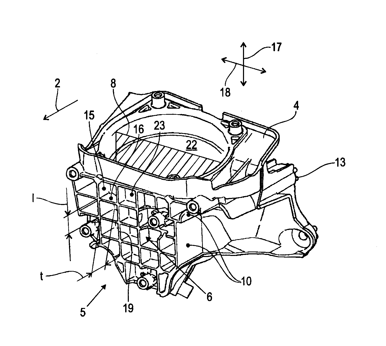
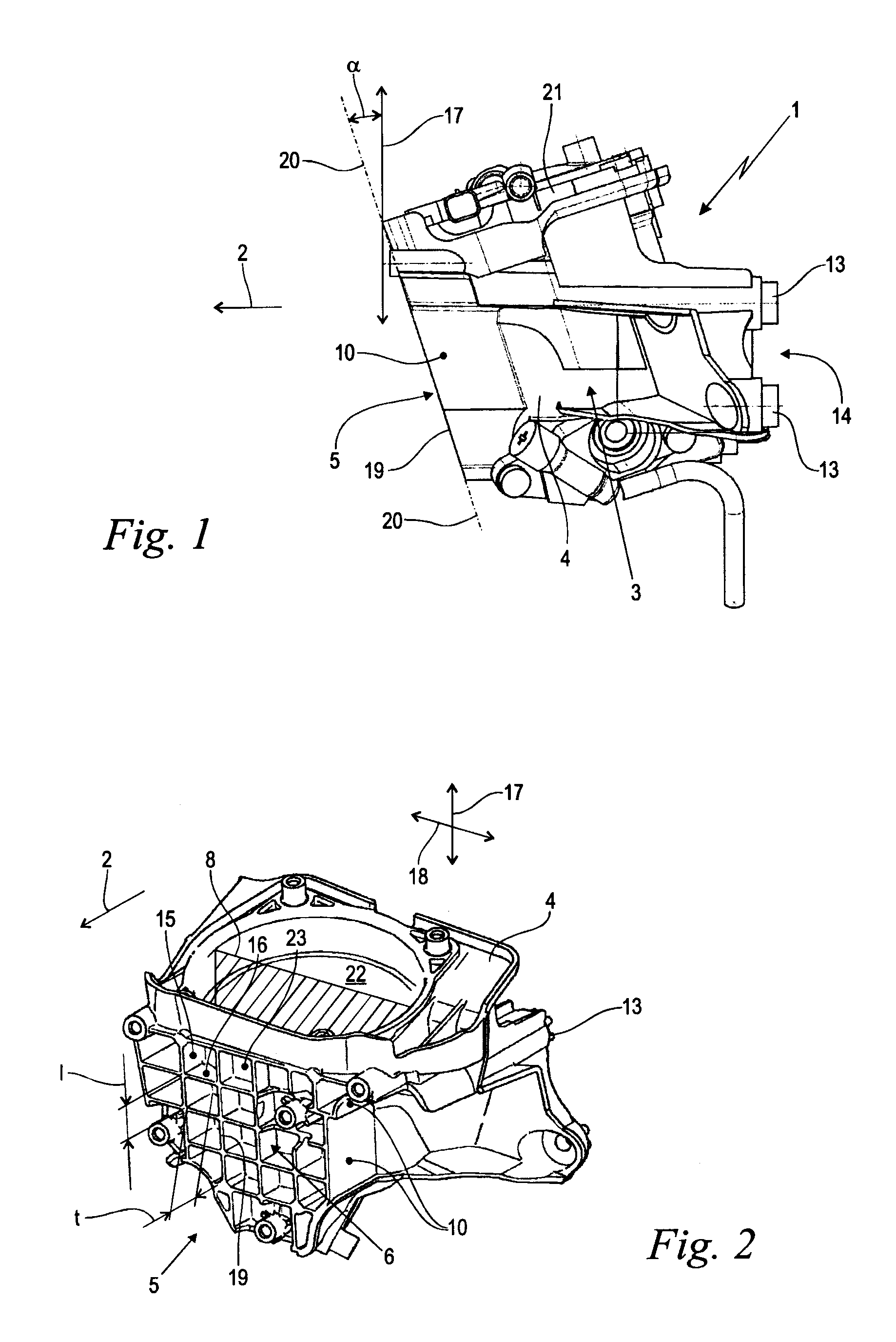
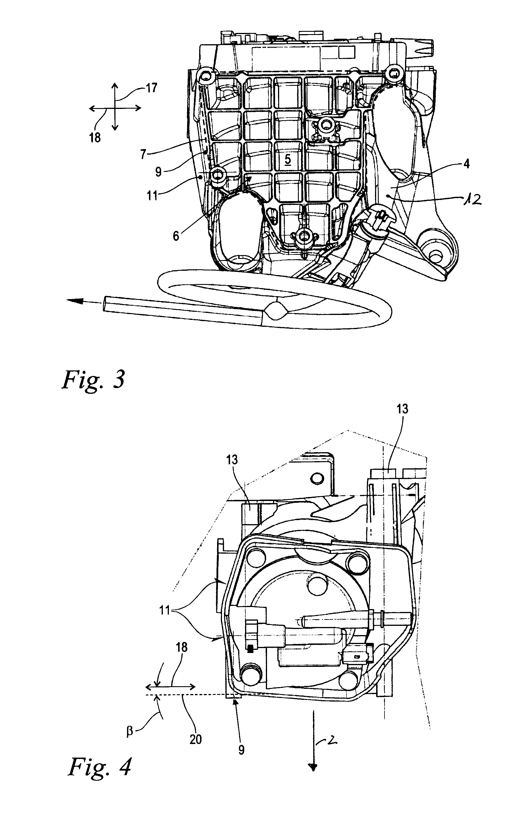
[0009]A fuel filter is proposed whose housing base body is provided externally at the front side with an integrally formed rib structure in the vehicle traveling direction or in potential force-loading direction in which the rib structure provides impact protection. Preferably, the rib structure is distributed across a rib surface area that is at least 80% and in particular at least 100% of a longitudinal section surface area of the filter interior of the housing base body as viewed in a direction opposite to the traveling direction or force loading direction. In the case of a suitable configuration, the rib structure is able to compensate point-shaped as well as more widely distributed impact loads. As a result of the integrally formed configuration these impact loads are distributed into the supporting walls of the housing base body while stress peaks are avoided. The aforementioned defined minimal size of the rib surface area contributes also to the prevention of stress peaks. Even for brittle materials such as die cast aluminum, crack formation under impact load is reliably prevented. The rib structure can be thin-walled and thus embodied in a material-saving way. Additional components such as separate crash armor are not required. As a whole, the invention yields an inexpensive lightweight configuration with high crash safety.
[0010]In an advantageous embodiment at least one lateral rib of the rib structure passes flush into a sidewall of the housing base body. Impact loads that mainly act opposite to the traveling direction or force introduction direction are immediately transmitted without deflection into the supporting sidewall of the housing base body. The sidewall is substantially loaded exclusively within its plane or surface. Transverse force components that can cause bending loads on the sidewall are substantially prevented. Even for a thin-walled configuration a high bearing capacity or crash safety is provided.
[0012]The rib structure can be configured expediently in accordance with different rib patterns. Preferably, ribs of the rib structure extend in a vertical direction as well as in a transverse direction on the front side. A grid pattern is produced which, on the one hand, is of a lightweight configuration and, on the other hand, is capable of compensating the occurring impact loads areally. The generation of local force and stress peaks is avoided. In this connection, the ribs can be arranged in a triangular or honeycomb pattern. Preferably, they are arranged in a rectangular pattern so that an excellent ratio of employed material and weight relative to the obtainable protective action results.
[0013]In a preferred embodiment, at least one part of the ribs and / or the lateral ribs have a depth that is at least 50% of a corresponding free length of the ribs and / or lateral ribs and in particular is at least as large as the free length. In this way, a sufficiently fine rib pattern with high stiffness and strength is produced. It is ensured that the impact load in a crash situation acts indeed on the ribs while the intermediately positioned thin wall sections of the housing base body are protected from direct contact.
[0014]It can be expedient to arrange the ribs in such a way that their nose edges at the front side define a curved, for example, cylindrical, surface. Preferably, the nose edges, at least approximately, are positioned in a rib plane. In this way, an areal force introduction and a uniform stress distribution within the material is favored.

Problems solved by technology

The available mounting space in the engine compartment is becoming increasingly tight and, as a result, such fuel filters are installed very close to the front end in the engine compartment where they are exposed to potential damage from crash loads.
A disadvantage is in the high manufacturing costs.
Such components are however relatively brittle and have no appreciable plastic yielding properties relevant in a crash situation.
Such a component is effective with regard to its function but causes additional costs and undesirable additional weight.

Method used


Image

  • Fuel filter of a motor vehicle
  • Fuel filter of a motor vehicle
  • Fuel filter of a motor vehicle

Examples


Embodiment Construction

[0024]Before describing in detail embodiments that are in accordance with the present invention, it should be observed that the embodiments reside primarily in combinations of apparatus components related to a fuel filter having a rib structure configured to provide crash load protection as disclosed herein. Accordingly, the apparatus components have been represented where appropriate by conventional symbols in the drawings, showing only those specific details that are pertinent to understanding the embodiments of the present invention so as not to obscure the disclosure with details that will be readily apparent to those of ordinary skill in the art having the benefit of the description herein.

[0025]In this document, relational terms such as first and second, top and bottom, and the like may be used solely to distinguish one entity or action from another entity or action without necessarily requiring or implying any actual such relationship or order between such entities or actions...


PUM

PropertyMeasurementUnit
anglesaaaaaaaaaa
anglesaaaaaaaaaa
angleaaaaaaaaaa

Abstract

A fuel filter of a motor vehicle is designed to be mounted in a traveling direction of the motor vehicle and has a filter housing with a housing base body. The housing base body has a front side facing in the traveling direction. The front side of the housing base body has an external, integrally formed rib structure configured and adapted as impact protection.

Description

CROSS REFERENCE TO RELATED APPLICATIONS[0001]This application claims the benefit under 35 USC 119 of the filing date of Federal Republic of Germany patent application no. DE 202008010506.4 filed Aug. 7, 2008, the entire disclosure of which is incorporated herein by reference.TECHNICAL FIELD[0002]This disclosure relates to a fuel filter of a motor vehicle.BACKGROUND OF THE INVENTION[0003]The invention relates to a fuel filter of a motor vehicle which fuel filter is adapted for being mounted in a traveling direction of the motor vehicle and comprises a filter housing with a housing base body. The housing base body has a front side that is facing in the traveling direction.[0004]Motor vehicles are provided with fuel filters for filtering the fuel supplied to the drive motor, wherein fuel filters of the aforementioned kind are mounted fixedly in the vehicle in a certain spatial orientation relative to the traveling direction of the vehicle. The available mounting space in the engine com...

Claims


Application Information

Patent Timeline
Patent Type & Authority Patents(United States)
IPC IPC(8): B01D35/30B01D35/31F02M37/32
CPCF02M37/22F02M37/32
Inventor KLUSON-HE.BETA.LINGER, HEIKEKRAFT, GUNTHER
Owner MANN HUMMEL GMBH
Why Eureka
Try Eureka