Separated water-storage type central hot water system for building

A hot water system and water storage technology, applied in residential hot water supply systems, household heating, heating methods, etc., can solve problems such as inconvenience for users to access hot water, increased production cost per ton of water, waste of water resources, etc. Achieve the effect of improving the efficiency of hot water production, reasonable energy consumption of pipelines, and reducing the production cost per ton of water.

Inactive Publication Date: 2011-06-08
潘戈
View PDF4 Cites 0 Cited by
  • Summary
  • Abstract
  • Description
  • Claims
  • Application Information

AI Technical Summary

Problems solved by technology

[0004](1) Too frequent instant auxiliary heating caused by unreasonable energy storage makes the system’s conventional auxiliary energy consumption and operating costs too high. Compared with the existing half-price peak-valley For the central solar water heating system with electric auxiliary heating, the output cost per ton of water is lower at 4-5 yuan. The cost will increase significantly, making it difficult for consumers to accept, and at the same time making the application and promotion of the existing system more resistant
[0005](2) When most of the existing residential buildings are added such as solar central heating system or heat pump central heating system for renovation, due to the fact that the ground floor of the existing building can be The utilization area is not enough to accommodate the large heating or hot water storage tank and constant temperature water supply tank. Therefore, the heating or hot water storage tank and constant temperature water supply tank of the system can only be installed on the top floor roof. The energy collector matrix competes for the area, and the overweight of the water tank of the system often leads to the overweight of the original roof and causes damage such as cracking
[0006](3) When using cheap peak-valley electricity for auxiliary heating, the economical water supply due to the design of the public network is limited, and due to the use of the existing technology system Reasonable distribution of economical water supply lacks technical considerations. Although household users can set hot water meters, they have no freedom to choose the amount of hot water consumption. For example, household users cannot reasonably allocate a guaranteed amount of hot water supply , when the first user uses more, it will lead to insufficient water supply for the later user, and it is difficult to apportion the high-priced energy consumption of the instant auxiliary heating hot water supply part beyond the economical water supply design, which is also the reason why the current central hot water An important reason why the system solution is difficult to be popularized and applied
[0007](4) Simply enlarging the volume of the water tank for energy storage will lead to a sharp increase in the area occupied by the water tank. The inconsistency of the floor structure leads to a series of problems such as a substantial increase in construction costs and a decrease in the occupancy rate, which will also greatly increase the difficulty of popularizing and applying the above-mentioned central hot water system solution
[0008](5) In the existing system, when the constant temperature water supply tank is placed on the top floor to use the drop pressure, another problem is that, in order to obtain the effect of the system under pressure to supply hot water At the same time, the hot water in the public network becomes cold and warm water after losing heat, which is difficult to recycle, which makes it very inconvenient for users to use hot water, and often results in a waste of water resources

Method used


Image

  • Separated water-storage type central hot water system for building
  • Separated water-storage type central hot water system for building
  • Separated water-storage type central hot water system for building

Examples


Embodiment Construction

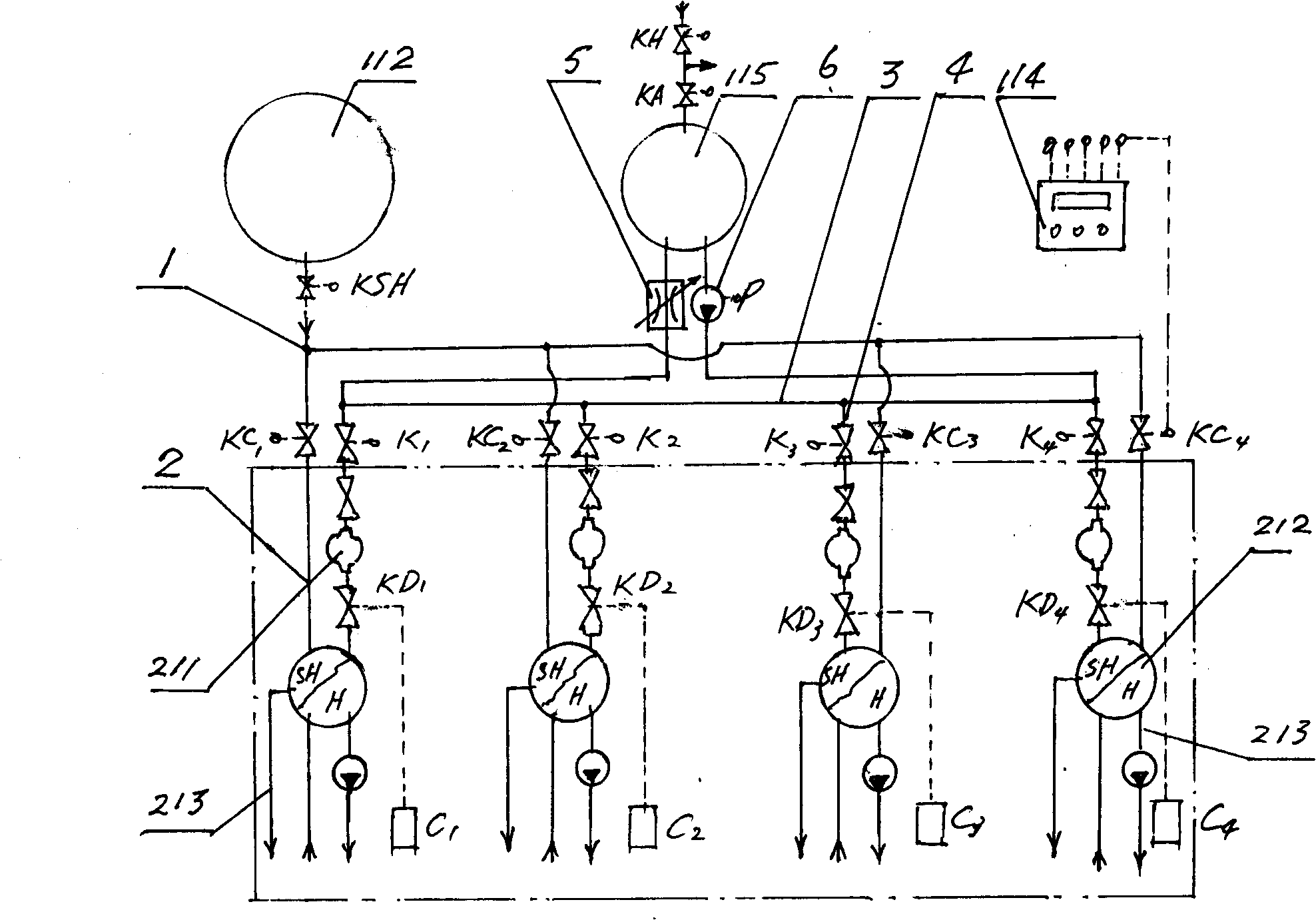
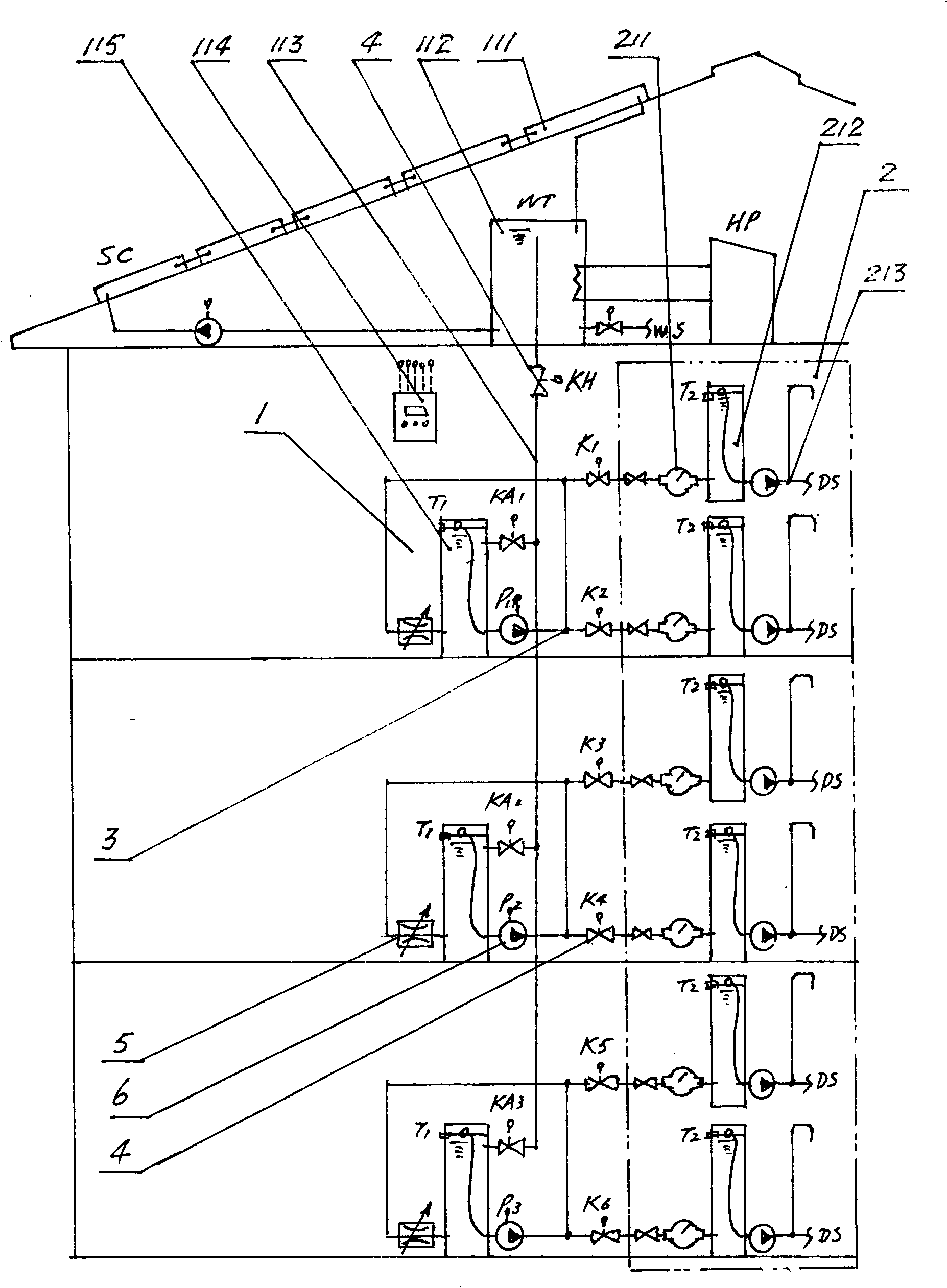
[0018] according to figure 2 and image 3As shown, one of the embodiments of the household water storage type central hot water system for residential buildings of the present invention is an open-type pressurized water supply central hot water system that uses solar energy or a heat pump and includes auxiliary heating energy as a heating unit, wherein the system consists of Composed of public network 1, private network 2, handover pipeline 3, electric control switch valve 4, pressure regulating valve 5, hot water distribution booster pump 6, etc., the public network part is heated by solar energy or heat pump or combined solar energy and heat pump HP Unit 111, heating or energy storage water tank 112, public network connection pipeline 113, control unit 114, layered final temperature water tank 115, etc., and its private network part consists of hot water meter 211, household hot water storage tank 212, It consists of hot water terminal pipelines and hot water use terminal ...


PUM


Abstract

The invention relates to a residential building central hot-water system of discrete storage mode. Public network of the system comprises water tank, pipes, heating unit, control unit and so on, and private network comprises hot-water meter, hot water terminal pipes of each discrete user terminal and discrete water storage tank arranged in each discrete user terminal. The public network and the private network are connected by pipe and electronic control switch valve, and the control unit controls the connection of the pipes for hot water distribution form the public network to the private network by the electronic control switch valve. By using the said structure, the system can guarantee the preferential supply for the discrete users and improve hot water producing efficiency and reducecost per ton, and users have freedom on configuration selection, and pipe energy consumption can be reasonably prorated, and the concentration level of water tanks on top floor and adverse effect caused by overweight can be improved, and the system is compatible with the practical reformation condition of the system of the established resident.

Description

technical field [0001] The invention belongs to the technical field of renewable energy utilization and energy saving, and in particular relates to a household water storage central hot water system for residential buildings which uses renewable energy and conventional energy as heating energy. Background technique [0002] So far, the heating energy used by the central hot water system of existing residential buildings includes the use of renewable energy and conventional energy. Among them, the most common central hot water system using renewable energy is a solar central hot water system or a heat pump central hot water system. The design structure of household water supply central hot water system in existing residential buildings can be divided into closed pressurized water supply system and open pressurized water supply system. It is not commonly used, and the typical system structure of the open pressurized water supply system can be found in figure 1 As shown, it ca...

Claims


Application Information

Patent Timeline
Patent Type & Authority Patents(China)
IPC IPC(8): F24D17/00
Inventor 潘戈
Owner 潘戈
Why Eureka
Try Eureka