Combustion gas kitchen range

A technology for gas stoves and burners, which can be used in the direction of household stoves/stoves, stoves/stove tops, heating fuel, etc., and can solve problems such as position deviation of brackets

Inactive Publication Date: 2008-05-28
RINNAI CORP
View PDF2 Cites 5 Cited by
  • Summary
  • Abstract
  • Description
  • Claims
  • Application Information

AI Technical Summary

Problems solved by technology

Therefore, when the position of the panel deviates from the burner due to deviation of the p

Method used


Image

  • Combustion gas kitchen range
  • Combustion gas kitchen range
  • Combustion gas kitchen range

Examples


Embodiment Construction

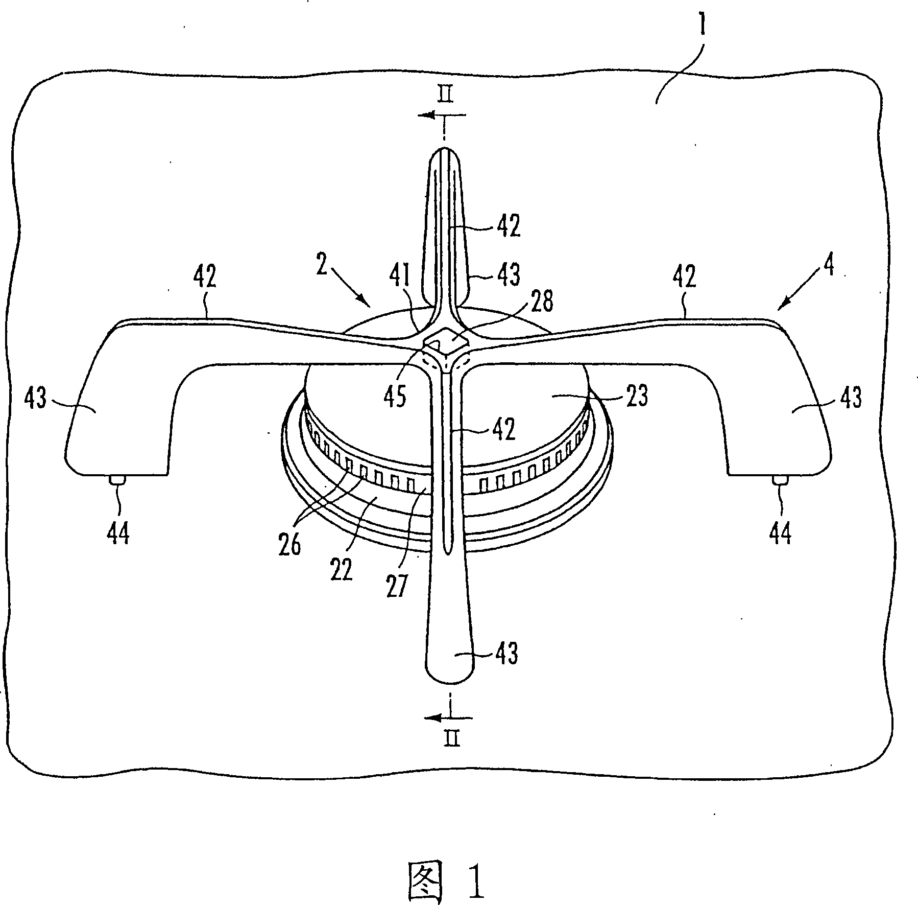
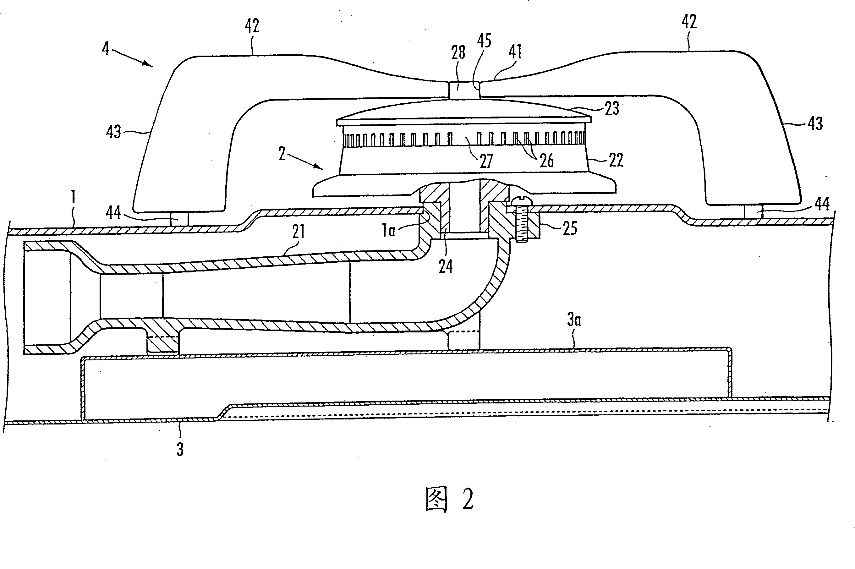
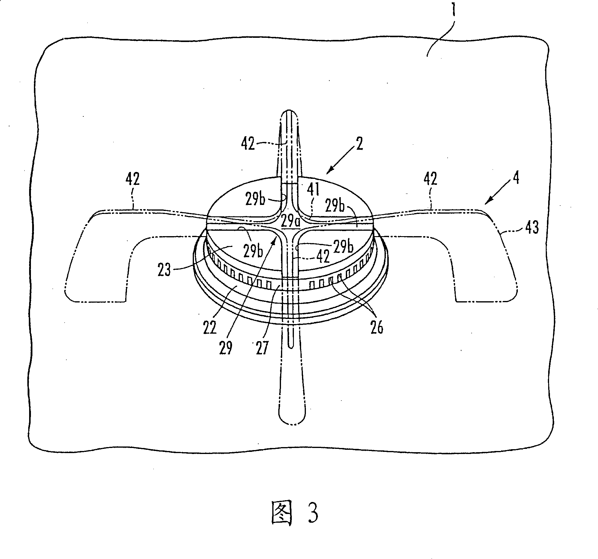
[0020] With reference to Fig. 1, 1 is the panel of gas stove, and 2 is burner. The burner 2, as shown in Figure 2, consists of a mixing tube 21 arranged in the stove body 3 covered by the panel 1, a burner body 22 protruding above the panel 1, and a burner head placed on the burner body 22 23 poses.

[0021] The mixing tube 21 is placed on the bottom frame 3a provided on the bottom of the stove main body 3 and fixed. In the range main body 3 , a gas nozzle, which is omitted from the illustration, is provided facing the upstream end of the mixing tube 21 . The mixed gas (mixed gas) of the gas injected from the gas nozzle and the primary air sucked in from the upstream end of the mixing tube 21 is generated in the mixing tube 21 . The downstream end portion of the mixing tube 21 is bent upward, and fitted into a through hole 1 a formed in the panel 1 . A cylindrical portion 24 vertically provided under the burner main body 22 is fitted to the downstream end portion of the mix...


PUM


Abstract

The invention provides a fuel gas stove which is provided with a burner (2) extruded to the top of a faceplate (1) and a bracket (4) arranged at the faceplate, directly confirming the position of the bracket corresponding to the burner. The bracket (4) is provided with a central connecting part (41) at the top of the burner and a plurality of bracket claws (42) extending to the radial outside of the central connecting part. The central connecting part of the bracket (4) forms a positioning hole (45) penetrating up and down and the top of the burner is provided with a heave (28) embedded in the positioning hole. The cross section shape of the embossment and the positioning hole is that the embossment (28) can be embedded in the positioning hole (45) only when the bracket (4) is located at the standard phase position of the same position of a fireless hole (27) of the bracket claw (42) and the burner (2).

Description

technical field [0001] The invention relates to a gas stove with a burner protruding above the panel and a bracket arranged on the panel 5 . Background technique [0002] Conventionally, in gas cooktops, a bracket in which a plurality of bracket claws are attached to a ring-shaped bracket frame is generally used. Also, a recessed portion is formed on the panel or a member fixed to the panel, and the recessed portion receives the engaging portion formed on the legs of the claws of the bracket. By engaging the engaging portion on the recessed portion, the position of the bracket can be determined (for example, Refer to Japanese Patent Application Laid-Open No. 2003-269731). [0003] Thus, it is preferable to arrange the bracket according to its predetermined positional relationship with respect to the burner. In the above-mentioned hitherto gas cookers, the position of the bracket relative to the burner is determined by means of the panel. Therefore, when the position of th...

Claims


Application Information

Patent Timeline
IPC IPC(8): F24C3/02F24C15/10
Inventor 水谷嘉宏吉冈敬祐
Owner RINNAI CORP
Why Eureka
Try Eureka