Valve gear of engine

A transmission device and engine technology, applied in the direction of engine lubrication, valve driving device, engine components, etc., can solve the problems that hinder the miniaturization of the engine and reduce the cost, and achieve good maintainability, simplified structure and miniaturization Effect

Inactive Publication Date: 2008-06-18
HONDA MOTOR CO LTD
View PDF1 Cites 5 Cited by
  • Summary
  • Abstract
  • Description
  • Claims
  • Application Information

AI Technical Summary

Problems solved by technology

Use of such an oil pump hinders miniaturization and cost reduction of the engine

Method used


Image

  • Valve gear of engine
  • Valve gear of engine
  • Valve gear of engine

Examples


no. 1 example

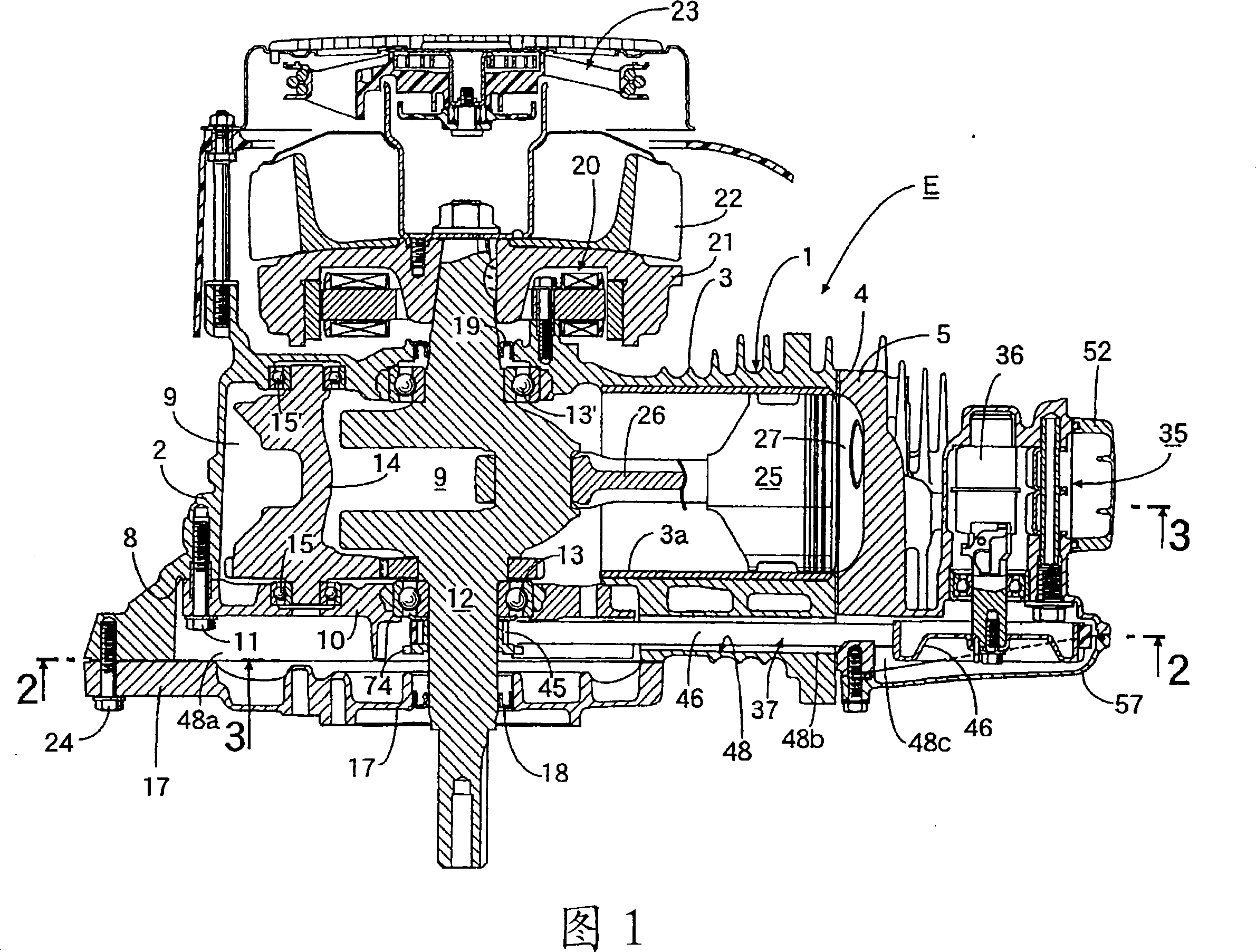
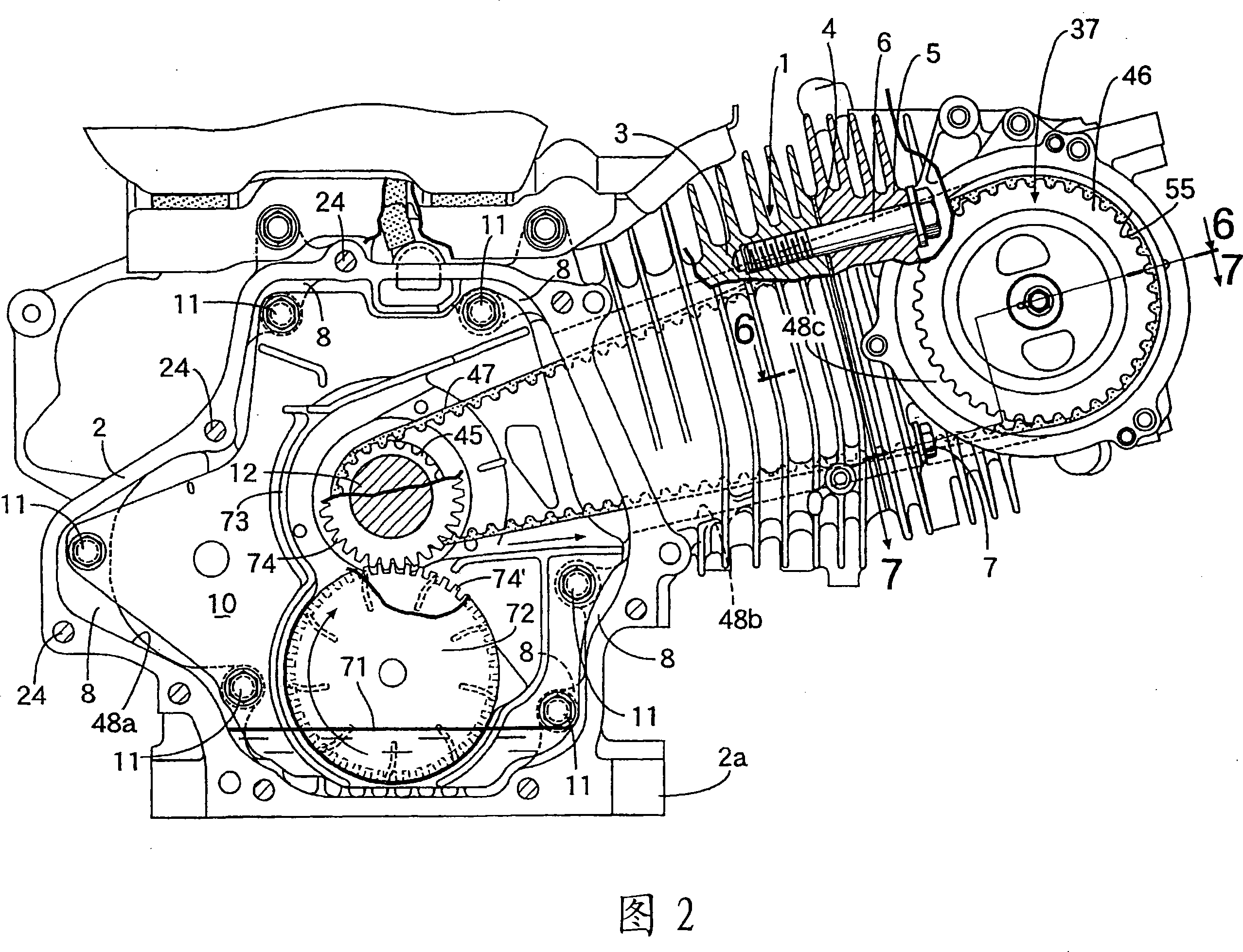
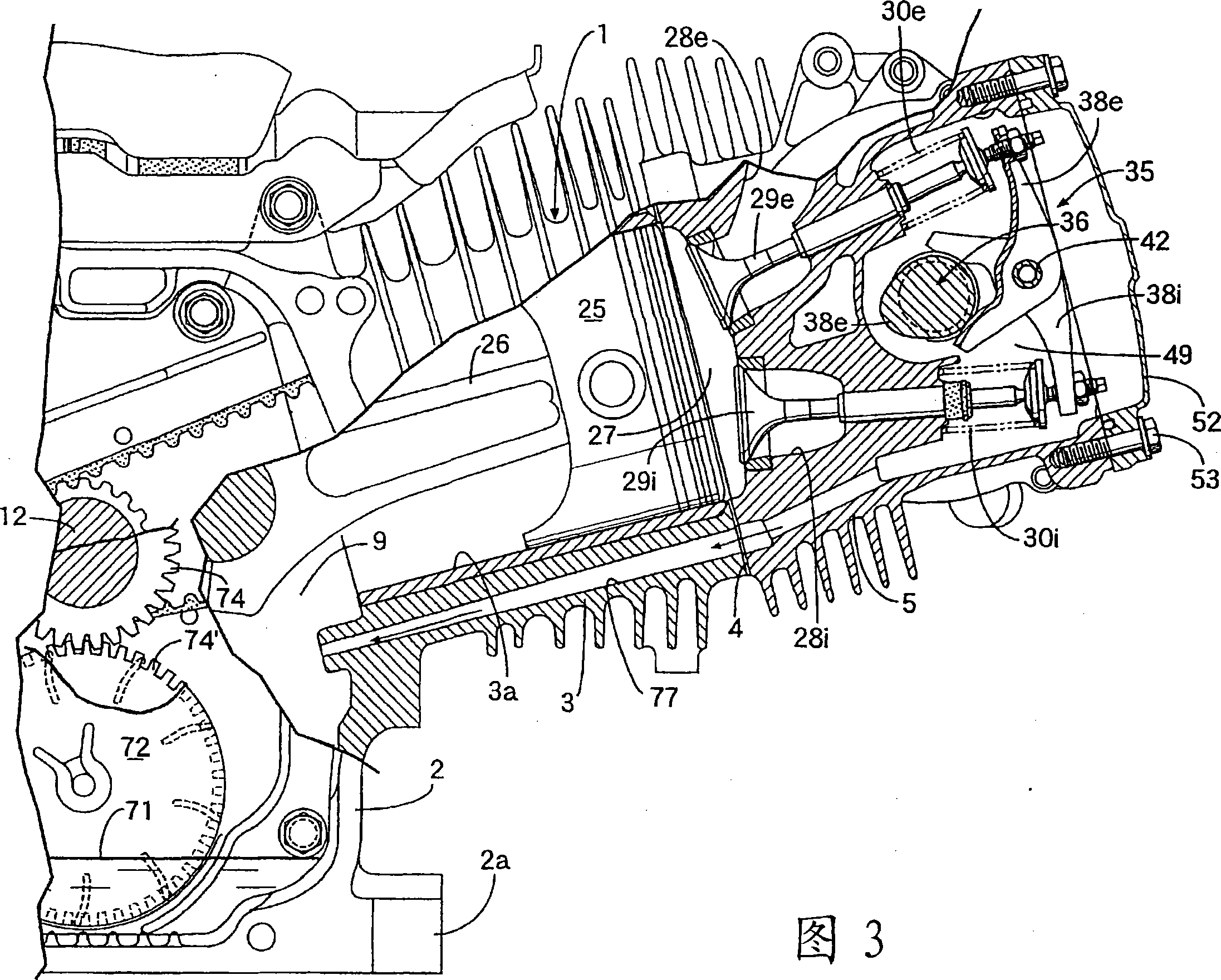
[0060] First, in FIGS. 1 to 4, the components of the engine body 1 of the general four-stroke engine E include: a crankcase 2 having a mounting seat 2a at the lower part; and a cylinder bore that is integrally connected with the crankcase 2 and has an upwardly inclined cylinder bore The cylinder block 3 of 3a; the cylinder head 5 joined to the upper end surface of the cylinder block 3 with the gasket 4 interposed between the cylinder head 5 and the cylinder block 3 is used in four positions around the cylinder bore 3a. The four main connecting bolts 6, 6... and the two auxiliary connecting bolts 7, 7 described later.

[0061]The crankcase 2 has one side open, and on the inner peripheral wall slightly inside from the open surface, a plurality of stepped portions 8, 8... which are arranged in the circumferential direction toward the open surface side are integrally formed, and these stepped portions 8 , 8... The bearing bracket 10 is fixed by a plurality of bolts 11, 11... Both ends...

no. 2 example

[0103] Next, another embodiment of the present invention shown in FIG. 13 will be described.

[0104] For this embodiment, a check valve 79 is provided in the oil passage 75 that communicates between the timing transmission chamber 48 and the valve transmission chamber 49. The check valve 79 only allows the passage from the valve transmission chamber 49 to the timing transmission chamber. 48 transfer negative pressure. The other structure is the same as that of the above-mentioned embodiment, so the parts in FIG. 13 corresponding to the above-mentioned embodiment are assigned the same reference numerals, and their description is omitted.

[0105] In this embodiment, when the pulsating pressure generated in the crank chamber 9 is transmitted to the valve transmission chamber 49, only the negative pressure therein acts on the timing transmission chamber 48 through the check valve 79, so the negative pressure can be The oil mist in the timing transmission chamber 48 is efficiently su...


PUM


Abstract

The present invention provides a valve transmission device for an engine. A crankshaft (12) and a camshaft ( 36) between the timing transmission device (37), the two ends of the camshaft (36) are connected by a side wall (5a) of the cylinder head (5) and a branch adjacent to the timing transmission chamber (48). The partition wall (5b) is supported, and between the above-mentioned side wall (5a) and the partition wall (5b), a valve transmission chamber (49) for accommodating the camshaft (36) is separated. The lower part of the transmission chamber (48) is equipped with an oil throwing ring (72), and the above-mentioned partition wall (5b) is provided with a passage for guiding the splash oil thrown off at the upper part of the timing transmission device (37) to the valve transmission chamber (49). The oil hole (75), and an oil return passage (77), which transmits the pulsating pressure of the crankshaft chamber (9) to the valve transmission chamber (49) and makes the oil stored in the valve transmission chamber (49) flow down to the crankshaft The crank chamber (9) inside the case (2). As a result, the arrangement of the camshaft overhead relative to the intake and exhaust valves can be maintained, and the timing transmission chamber and the valve transmission chamber, which are separated from each other, can be lubricated without using an oil pump.

Description

Technical field [0001] The present invention relates to an improvement of a valve transmission device of an engine as follows: a timing transmission device is housed in a timing transmission chamber formed on one side of the engine main body composed of a crankcase, a cylinder block, and a cylinder head. The device connects the crankshaft supported on the crankcase and the camshaft supported on the cylinder head by the tops of the intake and exhaust valves. Both ends of the camshaft are formed on the cylinder head by a side wall of the cylinder head and The partition wall adjacent to the timing transmission chamber is supported, and a valve transmission chamber accommodating the camshaft is defined between the one side wall and the partition wall. Background technique [0002] The valve train of the engine described above is already known as disclosed in Patent Document 1. [0003] Patent Document 1: Japanese Patent Application Publication No. 61-182406 [0004] In the above-ment...

Claims


Application Information

Patent Timeline
Patent Type & Authority Applications(China)
IPC IPC(8): F01M9/10F01M1/04F01M1/06F01M1/16F01M9/06
CPCF01L1/047F01L1/02F01L13/08F01L1/181F01M9/10F01L13/085F01M9/06F01L2001/0476F01L1/024F01M1/04F01M1/16
Inventor 佐藤义一川口昇
Owner HONDA MOTOR CO LTD
Why Eureka
Try Eureka