

Routing switching device, method and switching cable fastener plate
A technology for switching line cards and switching devices, applied in the field of communication, which can solve the problems of many devices, complicated management, and high cost
Active Publication Date: 2008-10-29
北京紫光通信科技集团有限公司
View PDF0 Cites 67 Cited by
- Summary
- Abstract
- Description
- Claims
- Application Information
AI Technical Summary
Problems solved by technology
In this way, on the one hand, there are many devices that need to be maintained, and the management is complicated; on the other hand, different devices need to be purchased separately, and the cost is high
Method used
View moreImage
Smart ImageViewing Examples

Examples
Embodiment Construction
Login to View More PUM
 Abstract
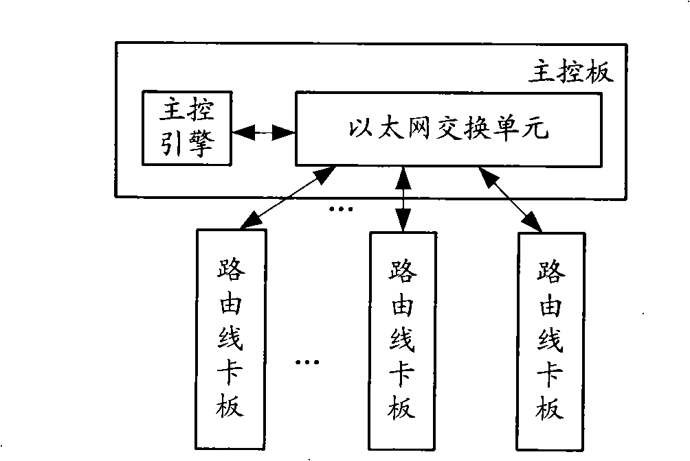
The invention discloses route switching equipment, a switching line card and a route switching method, wherein, the route switching equipment comprises an Ethernet switching unit, a route line card and the switching line card comprising a Layer 2 switching chip / a Layer 3 switching chip, wherein, message transmission between the switching line cards, and between the switching line card and the route line card is carried out by the Ethernet switching unit. The technical proposal disclosed by the invention can lower the complexity of management.
Description
Routing switching equipment, method and switching line card board Technical field The present invention relates to the field of communication technology, in particular to a routing and switching device, a method and a switching line card board. Background technique The router is the third layer (L3) of the OSI (Open System Interconnection) protocol model, that is, the packet switching equipment (or network layer relay equipment) in the network layer. The routing technology consists of two most basic activities, namely, determining the most Optimal path and transmission data packets, namely IP packets. After the router receives the message, it first removes the header of the link layer (unpacking), reads the destination address, and then looks up the routing table. If it can determine where to send it next, add the header of the link layer ( Package), forward the message to the next router that can reach the destination. When the next router receives the message, it will also che...
Claims
Login to View More Application Information
Patent Timeline
 Patent Type & AuthorityApplications(China)
IPC IPC(8): H04L12/56H04L29/06H04L12/773
Inventor杨武
Owner北京紫光通信科技集团有限公司