Routing switching device, method and switching cable fastener plate

A technology for switching line cards and switching equipment, applied in the field of communications

Active Publication Date: 2010-12-22
北京紫光通信科技集团有限公司
View PDF6 Cites 2 Cited by
  • Summary
  • Abstract
  • Description
  • Claims
  • Application Information

AI Technical Summary

Problems solved by technology

In this way, on the one hand, there are many devices that need to be maintained, and the management is complicated; on the other hand, different devices need to be purchased separately, and the cost is high

Method used


Image

  • Routing switching device, method and switching cable fastener plate
  • Routing switching device, method and switching cable fastener plate
  • Routing switching device, method and switching cable fastener plate

Examples


Embodiment Construction

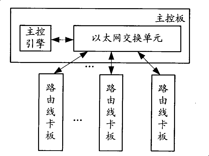
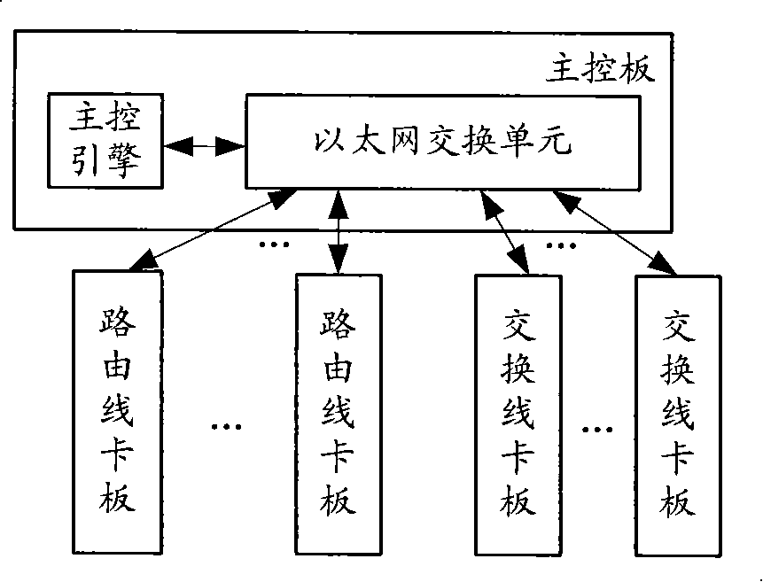
[0070] Wherein, the main control board includes a main control engine and an Ethernet switching unit, the main control engine is connected to the Ethernet switching unit, and the Ethernet switching unit is respectively connected to each routing line card board and switching line card board. The switch line card includes an L2 / L3 switch chip. Among them, in addition to the packet forwarding between the routing line card boards through the Ethernet switching unit, the packet forwarding is performed between the switching line card boards, between the switching line card board and the routing line card board through the Ethernet switching unit .

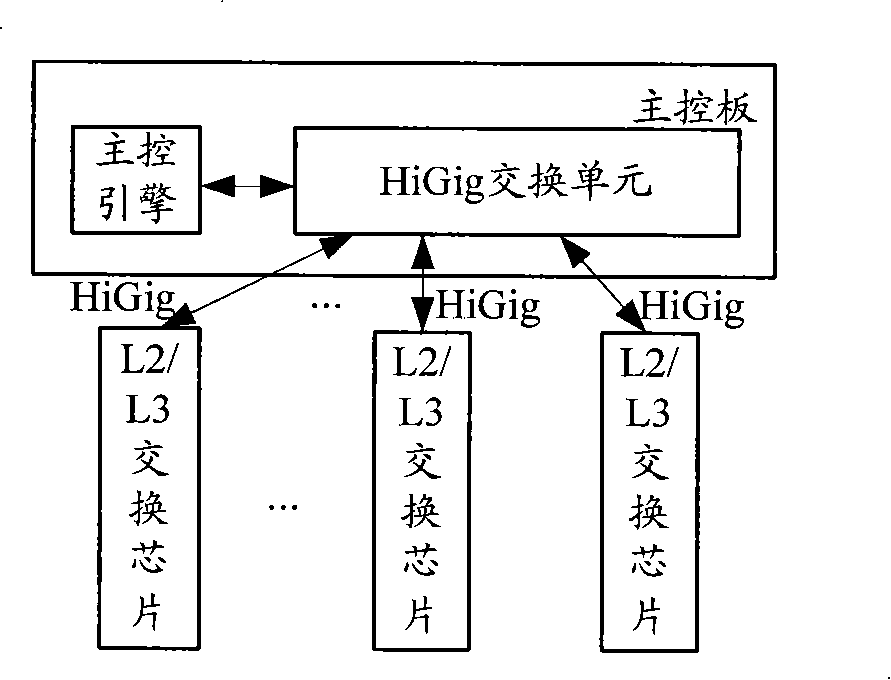
[0071] During specific implementation, the L2 / L3 switching chip in the switching line card board can be directly connected to the Ethernet switching unit through the Ethernet, and at this time, the switching line card boards, the switching line card board and the routing line card board can be Based on the existing Ethernet protocol, th...


PUM


Abstract

The invention discloses route switching equipment, a switching line card and a route switching method, wherein, the route switching equipment comprises an Ethernet switching unit, a route line card and the switching line card comprising a Layer 2 switching chip / a Layer 3 switching chip, wherein, message transmission between the switching line cards, and between the switching line card and the route line card is carried out by the Ethernet switching unit. The technical proposal disclosed by the invention can lower the complexity of management.

Description

technical field [0001] The invention relates to the technical field of communication, in particular to a routing switching device, a method and a switching line card board. Background technique [0002] A router is the third layer (L3) of the OSI (Open System Interconnection) protocol model, that is, a packet switching device (or network layer relay device) in the network layer. Routing technology consists of two most basic activities, namely, determining the most The optimal path and transmission data packets, that is, IP packets. After the router receives the packet, it first removes (unpacks) the packet header of the link layer, reads the destination address, and then searches the routing table. If it can determine where to send it next, it adds the packet header of the link layer ( package), and forward the message to the next router that can reach the destination. When the next router receives the message, it will also check its destination address and use an appropr...

Claims


Application Information

Patent Timeline
Patent Type & Authority Patents(China)
IPC IPC(8): H04L12/56H04L29/06H04L12/773
Inventor 杨武
Owner 北京紫光通信科技集团有限公司
Why Eureka
Try Eureka