Axial gap type eccentric rotor and axial gap type coreless vibrating motor using said rotor

An eccentric rotor and gap-type technology, which is applied in the direction of electric components, fluids using vibration, electrical components, etc., can solve the problems that it is difficult to ensure the impact resistance strength of the eccentric hammer, and achieve the effect of preventing falling off and ensuring impact resistance

Inactive Publication Date: 2008-12-24
TOKYO PARTS IND CO LTD
View PDF3 Cites 3 Cited by
  • Summary
  • Abstract
  • Description
  • Claims
  • Application Information

AI Technical Summary

Problems solved by technology

[0009] However, due to the thinning intention of recent portable devices, the vibration motor functioning as a mounted silent notification source is also required to have

Method used


Image

  • Axial gap type eccentric rotor and axial gap type coreless vibrating motor using said rotor
  • Axial gap type eccentric rotor and axial gap type coreless vibrating motor using said rotor
  • Axial gap type eccentric rotor and axial gap type coreless vibrating motor using said rotor

Examples


Embodiment 1

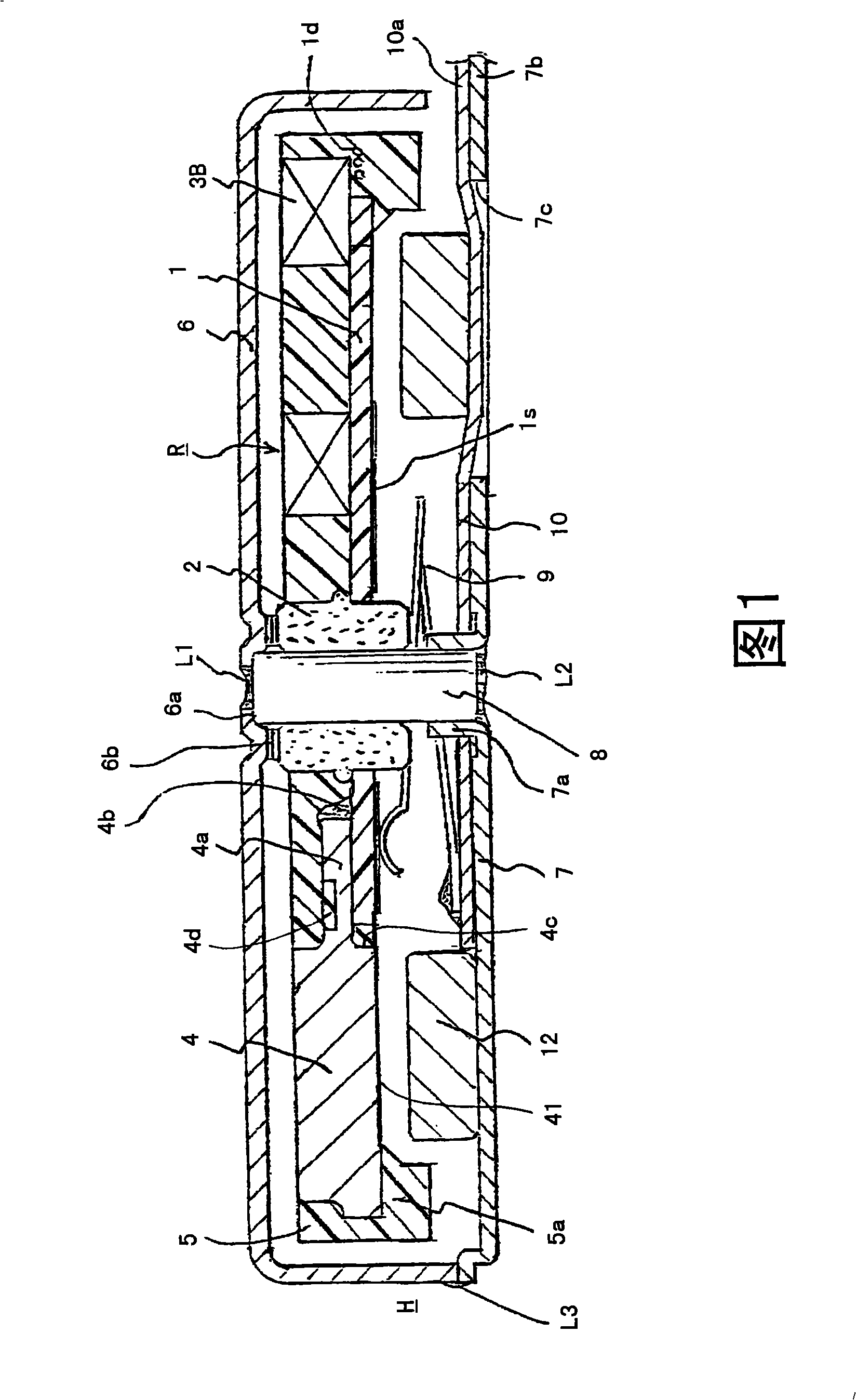
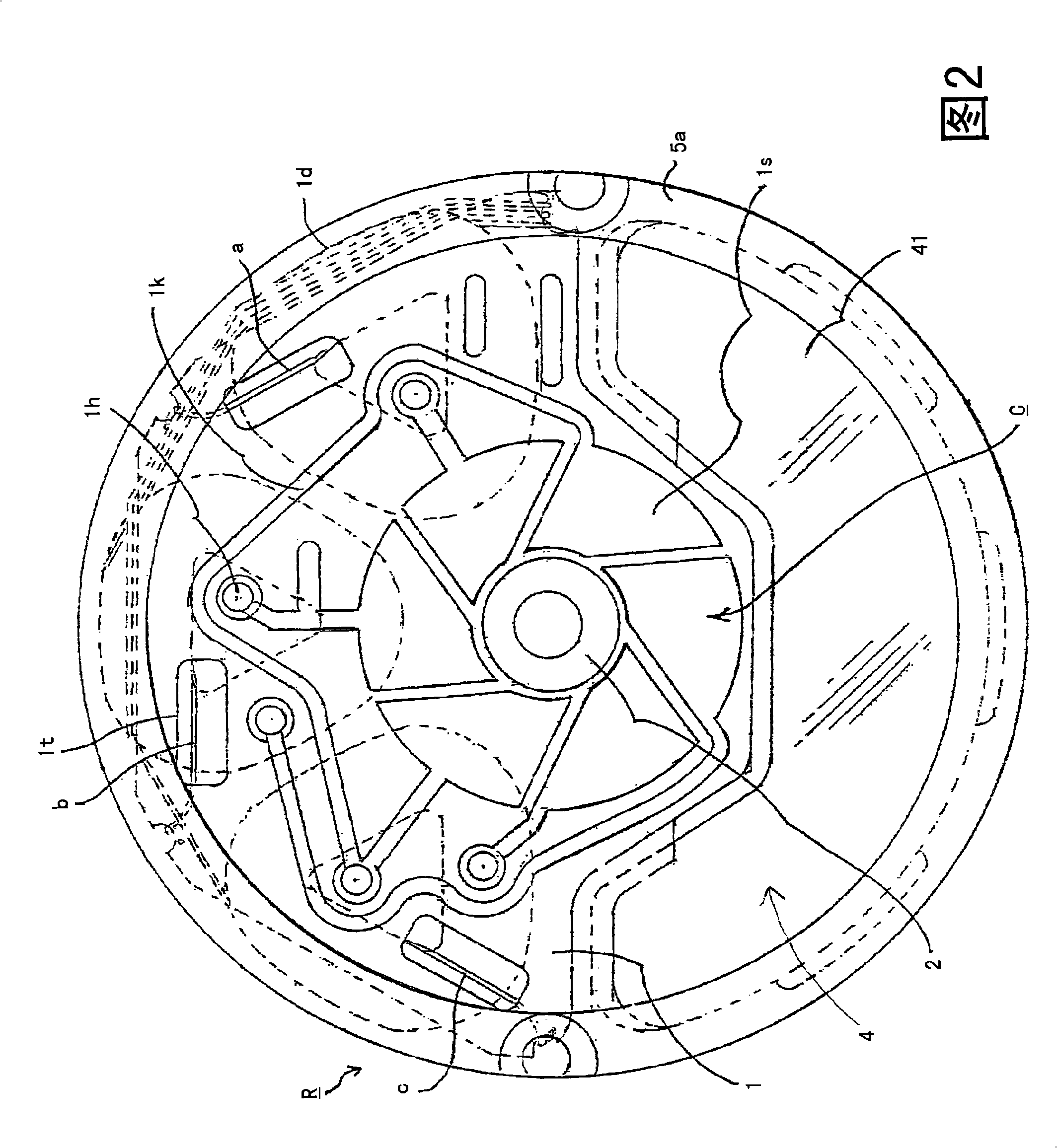
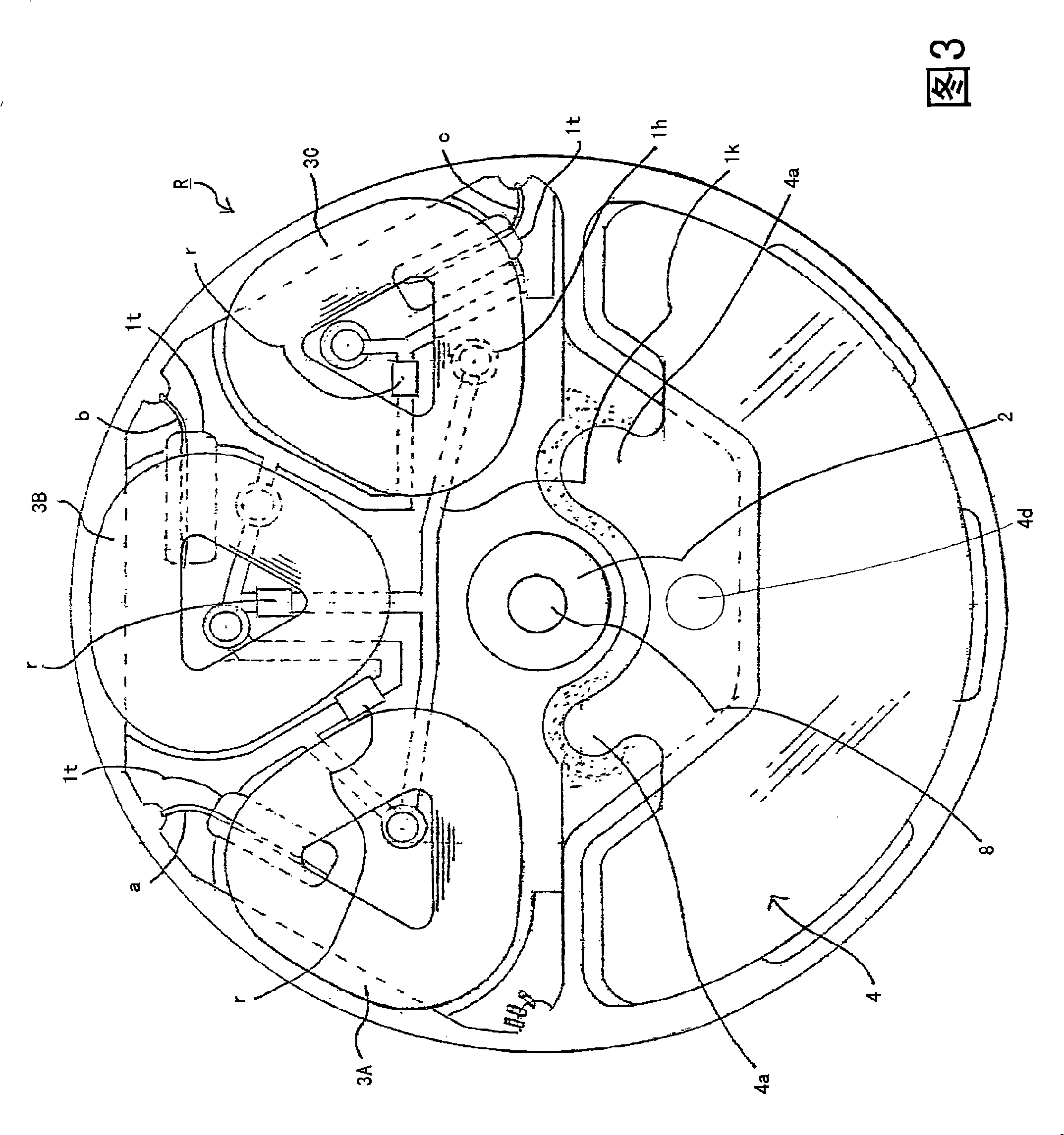
[0029] As the axial gap type rotor of the present invention, a rotor composed of an eccentric rotor for generating vibration will be described here.

[0030] In FIGS. 1 to 3 , a printed circuit board 1 made of a glass fiber cloth epoxy substrate is formed in an expanded fan shape, and a bearing 2 as a shaft support is arranged in the center. A six-pole sector land (land) 1s is formed on one surface side of the outside of the bearing 2 , and the converter C is formed by plating several micrometers of gold on the surface. The segment lands 1 s of the converter are connected to each other by a short-circuited wire land 1 k via vias 1 h. Three long holes 1t are formed on the outside to the inner diameter of the winding so that the winding start ends a, b, and c of the wire-wound hollow armature windings 3A, 3B, and 3C described later can be safely drawn out. On the other side of the printed circuit board 1, a wire bonding area is formed through a through hole 1h to short-circuit ...

Embodiment 2

[0036] Fig. 4 shows a modified example of the eccentric rotor. In order to increase the thickness of the wire-wound hollow armature winding in a limited gap to increase the output, and to achieve long life as a converter, the segments 13 of the converter are set at The thicker flat plate type with precious metal cladding on the surface, that is, the printed circuit board 11 is arranged inside these wire-wound type hollow armature windings in such a way that it does not overlap with the hollow armature winding 33, and the sector pieces 13 are soldered fixed on one surface. During this soldering, the positions of the respective wiring lands are re-determined, the solder lands are ensured, and the printed circuit board 11 is directly soldered on the inner side of the flat sliding joint. In this way, the segment piece 13 of the converter can be substantially set so as not to protrude from the lower surface of the rotor, and the sliding flexing stroke of the brush can be sufficient...


PUM


Abstract

The present invention provides an axial direction gap type eccentric rotor which can fully ensure thin type and strength based on a mounting structure of an eccentric weight, which comprises: winding type coreless armature windings (3A, 3B, 3C), a printed circuit board (1) arranged with a converter (C) on one side and connected with the end connection of the winding type coreless armature windings on the other side, an eccentric weight is soft soldering on the other side of the printed circuit board by a tongue (4a) on the printed circuit board, a bearing (2) arranged at the center of the printed circuit board and a resin (5) making them become one.

Description

technical field [0001] The present invention relates to the improvement of an axial gap type rotor suitable for use in a silent notification unit of a mobile communication device and an axial gap type motor provided with the rotor, and particularly relates to a mounting structure of an eccentric weight. Background technique [0002] As a silent notification unit of a mobile communication device, there is a vibration motor that vibrates by centrifugal force. Such vibration motors generally have a motor in which an eccentric weight having a cross section shaped like a ginkgo leaf is attached to an output shaft of a rotary cylindrical motor. In addition, the present applicant proposed that the built-in rotor itself vibrate by centrifugal force in an axial gap type flat motor. Since the rotor-built-in vibration motor does not require an output shaft, in recent years, a shaft-fixed motor that can eliminate one bearing has been used as a slave-rotation type. In such a shaft-fixe...

Claims


Application Information

Patent Timeline
IPC IPC(8): H02K23/58H02K7/065
CPCB06B1/04H02K5/163H02K7/065H02K7/085H02K23/54
Inventor 山口忠男
Owner TOKYO PARTS IND CO LTD
Why Eureka
Try Eureka