Frame head apparatus of translational rotary compressor

A rotary compressor, translational technology, used in rotary piston machinery, components of pumping devices for elastic fluids, rotary piston/oscillating piston pump components, etc., can solve the machine compression heat and friction. Heat can not be quickly discharged, the cylinder is bulky, and the heat dissipation performance is poor, so as to improve the heat dissipation effect and compression efficiency, simplify the processing technology, and improve the mechanical efficiency.

Active Publication Date: 2011-02-09
XINLEI COMPRESSOR CO LTD
View PDF2 Cites 0 Cited by
  • Summary
  • Abstract
  • Description
  • Claims
  • Application Information

AI Technical Summary

Problems solved by technology

However, the piston and the slide plate are integrated, which is difficult to process; the reciprocating space of the slide plate needs to be reserved inside the cylinder, which makes the cylinder bulky and easy to deform; due to structural limitations, the compression heat and friction heat generated by the machine cannot be quickly Discharge, poor heat dissipation performance

Method used


Image

  • Frame head apparatus of translational rotary compressor
  • Frame head apparatus of translational rotary compressor
  • Frame head apparatus of translational rotary compressor

Examples


Embodiment 1

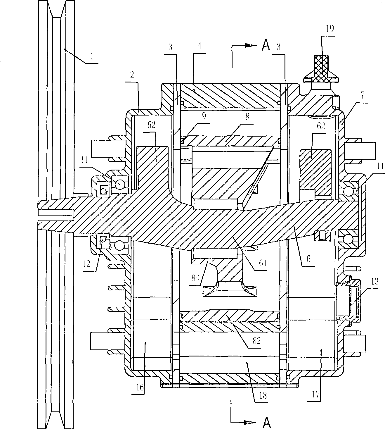
[0034] like figure 1 The machine head device of the translational rotary compressor shown, the device includes a cylinder body 4, a crankshaft 6, a transmission wheel 1, a slide plate 5 and a translational piston 8, and the two ends of the cylinder body 4 are respectively provided with a left end cover 2 and a right end cover 7 , the left end cover 2, the right end cover 7 and the cylinder body 4 are respectively provided with a piston baffle 3, the left end cover 2, the right end cover 7, the cylinder body 4 and the piston baffle 3 are fixedly connected by bolts, the left end cover 2 and the piston baffle 3. Sealing rings are respectively provided between the right end cover 7 and the piston baffle 3 , and between the cylinder body 4 and the piston baffle 3 . like figure 1 As shown, cavities are respectively formed between the left end cover 2, the right end cover 7 and the piston baffle 3, the bottom of the cylinder body 4 is provided with an oil groove 18, and the oil groo...

Embodiment 2

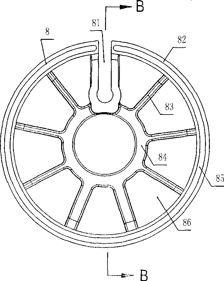
[0042] Such as Figure 5 , Figure 6 As shown, the translational piston 8 includes an inner wall body 84 and an outer wall body 82 , the inner wall body 84 and the outer wall body 82 are connected by a fixed panel 87 , and a plurality of cooling through holes 88 are provided on the fixed panel 87 . Other structural features are the same as in Embodiment 1.


PUM


Abstract

The invention relates to the air compression, fluid conveying and the evacuation fields, in particular to a rotary compression machine with a translational piston; the machine head device of the translational rotary compression device comprises a cylinder body, a crankshaft, a transmission wheel, a sliding plate, a translational piston; the transmission wheel is arranged on one end of the crankshaft; the middle part of the crankshaft is provided with an eccentric rotor; the rotary center of the eccentric rotor is concentric with the cylinder body; the translational piston is arranged on the eccentric rotor and is movably connected with the eccentric rotor; the lateral surface of the translational piston is tangent with the inner lateral surface of the cylinder body, so as to form a crescent-shaped operation cavity; one end of the sliding plate is hinged on the inner wall of the cylinder body; a sliding plate groove is arranged on the translational piston in the radial direction; the other end of the sliding plate is extended to the sliding plate groove through the operation cavity; the sliding plate is movably connected with the sliding plate groove the operation cavity is dividedinto an expansion cavity and a compression cavity by the sliding plate; a suction port and a discharge port are respectively on the expansion cavity and the compression cavity; The rotary compressionmachine with a translational piston has the advantages of simple structure and high operation efficiency.

Description

technical field [0001] The invention relates to the fields of gas compression, fluid delivery and vacuum pumping, in particular to a rotary compression machine with a translational piston. Background technique [0002] Gas compressors, fluid pumps and vacuum pumps are important general purpose compression machinery. At present, rolling piston compression machinery and rotor compression machinery, as representatives of the second generation of compression machinery, both have a crescent-shaped working chamber; the crescent-shaped working chamber is separated into an expansion chamber and a compression chamber by a slide plate; The moving piston) changes the volume of the expansion chamber and the compression chamber to realize the suction (liquid) and exhaust (liquid) of the compression machine. However, there is a problem in these two compression machines, that is, the sliding plate extends into the working chamber to isolate the expansion chamber and the compression chambe...

Claims


Application Information

Patent Timeline
Patent Type & Authority Patents(China)
IPC IPC(8): F04C29/00F04C18/332
Inventor 钟仁志
Owner XINLEI COMPRESSOR CO LTD
Why Eureka
Try Eureka