

Elevator control device
A control device and braking device technology, which is applied in the field of elevator control devices, can solve problems such as vibration, noise, and user anxiety
- Summary
- Abstract
- Description
- Claims
- Application Information
AI Technical Summary
Problems solved by technology
Method used
Image

Examples
no. 1 Embodiment approach
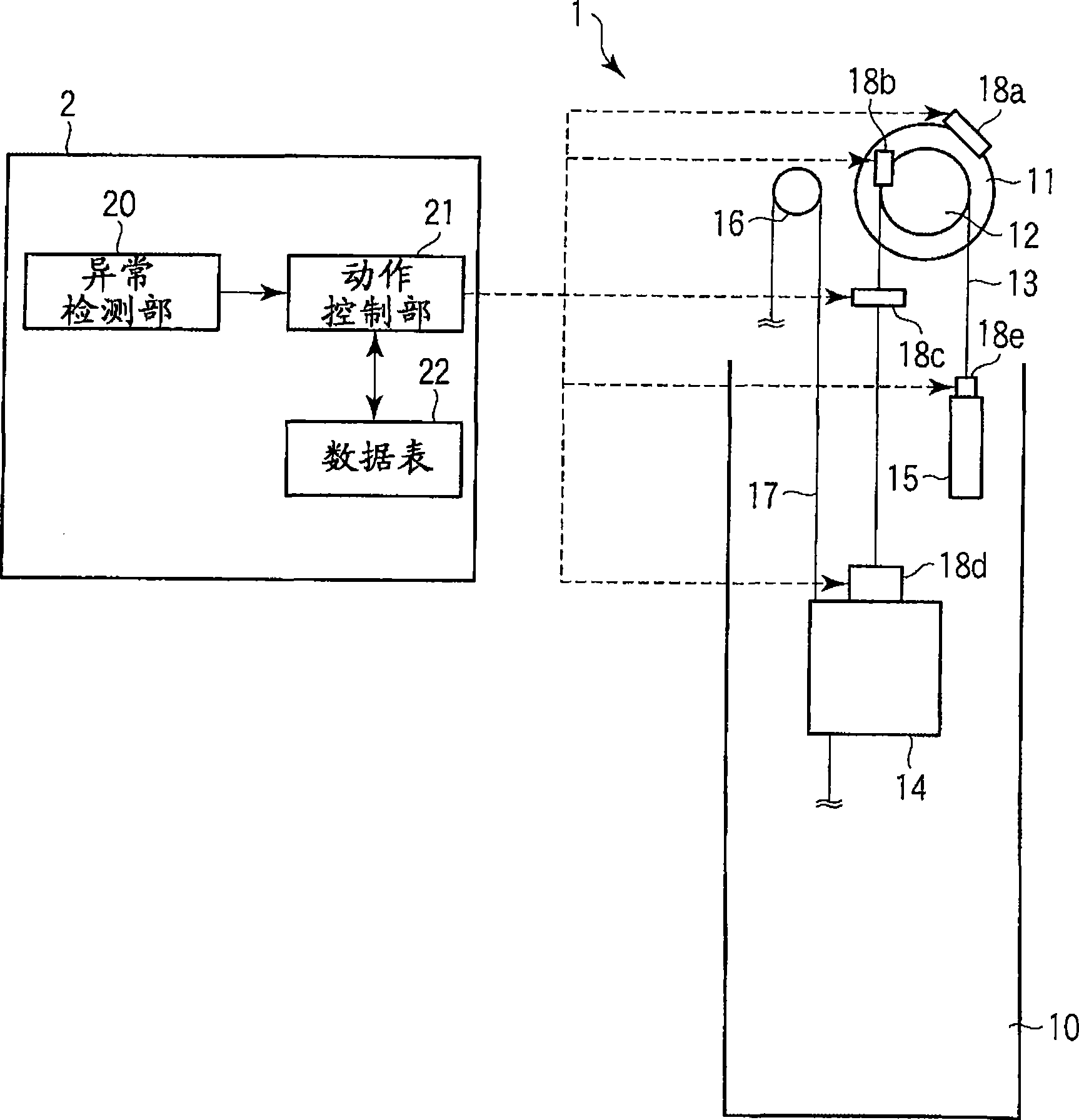
[0018] figure 1 It is a figure which shows the whole structure of the control apparatus of the elevator concerning 1st Embodiment of this invention. In the figure, 1 is an elevator installed in a building, and 2 is a control device for controlling the operation of the elevator 1 .
[0019] Elevator 1 comprises: traction machine 11, traction sheave 12, main traction rope 13, car 14, counterweight 15, regulator (governor) 16 and regulator rope 17.
[0020] The hoisting machine 11 is installed in a machine room or the like of a building, and is driven and controlled by commands from the control device 2 during operation of the elevator 1 . The traction sheave 12 is rotatably attached to the rotation shaft of the traction machine 11 . A plurality of main traction ropes 13 are wound around the circumference of the traction sheave 12 .
[0021] A car 14 is connected to one end of the main hoisting rope 13 , and a balance weight 15 is connected to the other end. When the traction...
no. 2 Embodiment approach
[0048] Next, a second embodiment of the present invention will be described.
[0049]In the second embodiment, the speed of the car 14 is added to control the operation of the brake devices 18a to 18e.
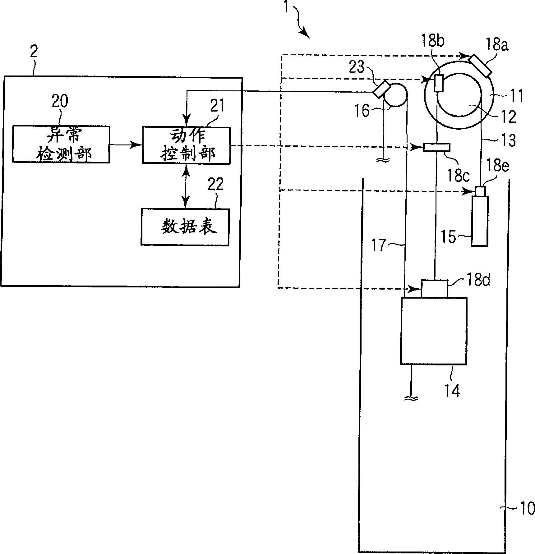
[0050] image 3 It is a figure which shows the whole structure of the control apparatus of the elevator concerning 2nd Embodiment of this invention. In addition, for the same as in the above-mentioned first embodiment figure 1 Parts having the same structure are assigned the same symbols, and descriptions thereof are omitted.
[0051] In the second embodiment, a speed detector 23 is provided on the governor (governor) 16 . The speed detector 23 calculates the speed of the car 14 from the rotation speed of the regulator 16 and outputs it to the operation control unit 21 of the control device 2 . Based on the speed of the car 14 obtained from the governor 16, the operation control unit 21 controls the operation of the braking devices 18a to 18e provided at various parts of t...
no. 3 Embodiment approach
[0063] Next, a third embodiment of the present invention will be described.
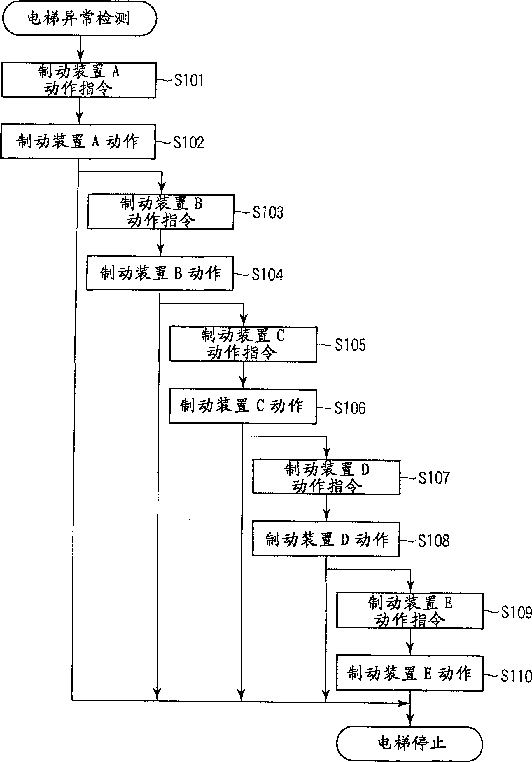
[0064] In the third embodiment, when each brake device 18a to 18e is operated in a predetermined order, the respective operating states are confirmed, and if there is a brake device that is not in operation, all the other brake devices are applied at this point in time. The device applies motion commands.
[0065] Figure 6 It is a figure which shows the whole structure of the control apparatus of the elevator concerning 3rd Embodiment of this invention. In addition, for the same as in the above-mentioned first embodiment figure 1 Parts having the same structure are assigned the same symbols, and descriptions thereof are omitted.
[0066] In the third embodiment, motion detection units 24a to 24e are provided on the brake devices 18a to 18e, respectively.
[0067] The operation detection unit 24a detects the operation state of the braking device 18a provided in the hoisting machine 11, and output...
PUM
 Abstract
Description
Claims
Application Information