Outboard motor control apparatus

a technology for controlling apparatus and motors, applied in the direction of marine propulsion, vessel construction, instruments, etc., to achieve the effect of preventing the occurrence of pitching and mitigate the feel of deceleration

Active Publication Date: 2011-12-01
HONDA MOTOR CO LTD
View PDF6 Cites 6 Cited by
  • Summary
  • Abstract
  • Description
  • Claims
  • Application Information

AI Technical Summary

Benefits of technology

[0007]An object of this invention is therefore to overcome the foregoing problem by providing an apparatus for controlling an outboard motor having a transmission, which apparatus can mitigate a deceleration feel generated when the gear position is changed upon the completion of the acceleration and prevent the pitching occurrence caused by the excessive trim-up operation.

Problems solved by technology

However, since the predetermined angle is set beforehand, it may cause excessive trim-up operation depending on size of the boat, resulting in occurrence of a failure such as pitching (vibration or shake in the vertical direction) of the boat, disadvantageously.

Method used


Image

  • Outboard motor control apparatus
  • Outboard motor control apparatus
  • Outboard motor control apparatus

Examples


first embodiment

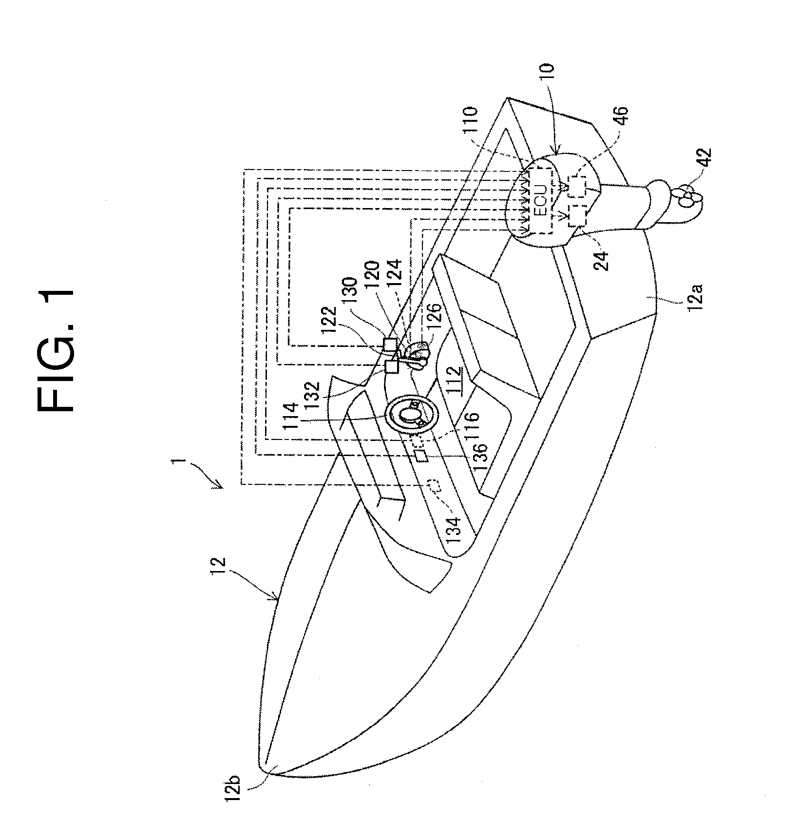
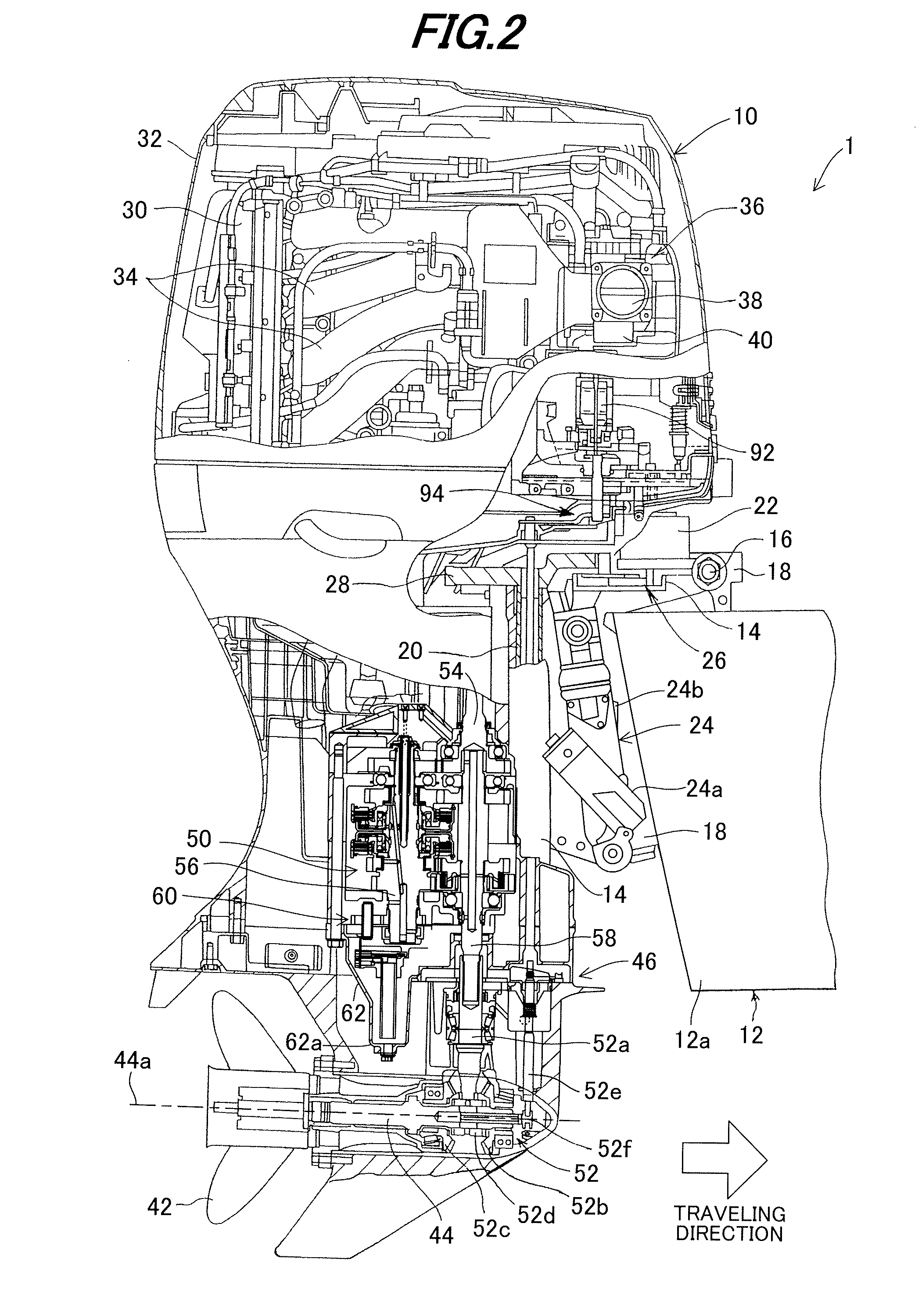
[0033]FIG. 1 is an overall schematic view of an outboard motor control apparatus including a boat according to the invention. FIG. 2 is an enlarged sectional side view partially showing the outboard motor shown in FIG. 1 and FIG. 3 is an enlarged side view of the outboard motor.

[0034]In FIGS. 1 to 3, a symbol 1 indicates a boat or vessel whose hull 12 is mounted with the outboard motor 10. As clearly shown in FIG. 2, the outboard motor 10 is clamped (fastened) to the stern or transom 12a of the boat 1, more precisely, to the stern 12a of the hull 12 through a swivel case 14, tilting shaft 16 and stern brackets 18.

[0035]An electric steering motor (actuator) 22 for operating a shaft 20 which is housed in the swivel case 14 to be rotatable about the vertical axis and a power tilt-trim unit (actuator; trim angle regulation mechanism; hereinafter called the “trim unit”) 24 for regulating a tilt angle and trim angle of the outboard motor 10 relative to the boat 1 (i.e., hull 12) by tiltin...

second embodiment

[0124]An outboard motor control apparatus according to the invention will be explained.

[0125]FIG. 12 is a flowchart similar to FIG. 6, but showing alternative examples of transmission control operation and trim angle control operation by the ECU 110. Note that the change switch 126 is positioned at the automatic speed change mode here.

[0126]The program begins at S10, in which the operation for determining which one from among the first to third speeds of the transmission 46 should be selected, is conducted.

[0127]FIG. 13 is a subroutine flowchart similar to FIG. 7, but showing the operation of the gear position determination.

[0128]The process of S400 to S406 is conducted similarly to S100 to S106 of the FIG. 7 flowchart.

[0129]When the result in S406 is negative, the program proceeds to S407, in which it is determined whether the bit of a rudder angle speed change flag indicating that the gear position is changed based on the rudder angle in the process which will be explained later, ...


PUM


Abstract

In an apparatus for controlling operation of an outboard motor having an internal combustion engine, transmission and trim angle regulation mechanism, it is configured to change a gear position to the first speed when the gear position is in the second speed and a throttle opening change amount is at or above a predetermined value, start trim-up operation when the engine speed is at or above a first predetermined speed after the gear position is changed to the first speed, change the gear position from the first speed to the second speed when the engine speed is at or above a second predetermined speed after the trim-up operation is started, and stop the trim-up operation after the gear position is changed to the second speed. It can mitigate a deceleration feel generated when the gear position is changed upon the completion of the acceleration and prevent the pitching occurrence.

Description

BACKGROUND OF THE INVENTION[0001]1. Technical Field[0002]This invention relates to an outboard motor control apparatus, particularly to an apparatus for controlling an outboard motor with a transmission.[0003]2. Background Art[0004]In recent years, there is proposed a technique for an outboard motor having a transmission interposed at a power transmission shaft between an internal combustion engine and a propeller to transmit an output of the engine to the propeller, as taught, for example, by Japanese Laid-Open Patent Application No. 2009-190671. In the reference, when the boat is accelerated through the manipulation of a throttle lever by the operator, a gear position (ratio) of the transmission is changed from the second speed to the first speed to amplify torque to be transmitted to the propeller, thereby improving the acceleration performance, and subsequently when the engine speed is increased so that the acceleration is completed, the gear position is returned from the first ...

Claims


Application Information

Patent Timeline
Patent Type & Authority Applications(United States)
IPC IPC(8): B63H21/21
CPCB63H20/10B63H2023/0266B63H21/265B63H20/14B63H20/20
Inventor KURIYAGAWA, KOJIYOSHIMURA, HAJIME
Owner HONDA MOTOR CO LTD
Why Eureka
Try Eureka