
Modular multi-axis motion control and driving system and method thereof

a multi-axis, driving system technology, applied in the direction of dynamo-electric converter control, electrical controller, programme control, etc., can solve the problems of reducing the performance of low frequency characteristics, the architecture is not ideal for industrial environments, and the use of distributed motion control systems is hot, so as to reduce wiring complexity, improve the integration of modules, and accelerate the development cycle

Inactive Publication Date: 2006-05-11
DYNACITY TECH HK
View PDF20 Cites 119 Cited by
  • Summary
  • Abstract
  • Description
  • Claims
  • Application Information

AI Technical Summary

Benefits of technology

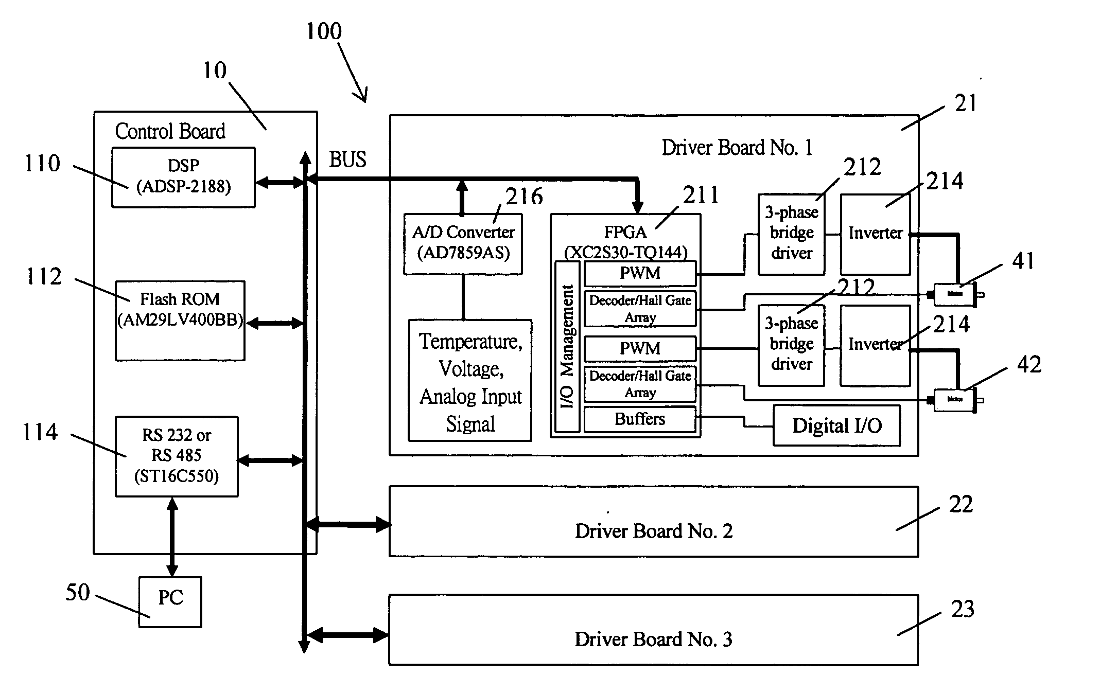
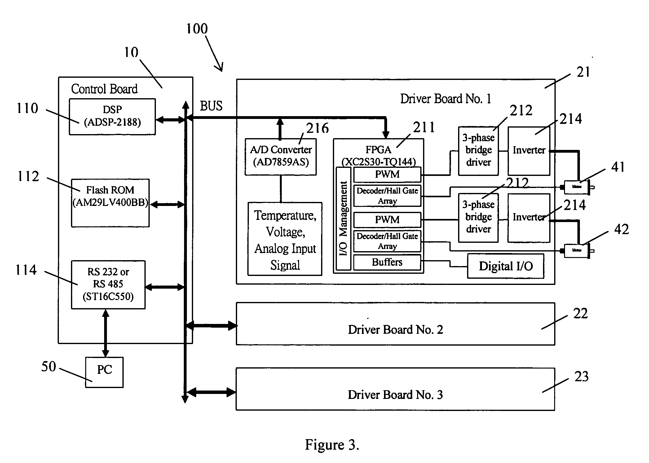
[0007] The second object of this invention is to provide a novel multi-axis motion control and driving system capable of integrating high performance motion control and servo amplifier together, which makes it possible to design high-frequency control loops and the dimension of the system is reduced to a great extent.
[0021] 3) Communication: Both RS232 and RS485 communications are provided by this system. The RS485 communication provides more powerful communication speed and communication length.
[0024] The developed products have the following three unique advantages compared to all other commercial products in the world today: 1) Employing high integration module by integrating motion control and power amplifier into one unit to achieve space saving, reduced wiring complexity, and faster development cycles; 2) Employing fully-digitalized control and driving technology and providing two digital control loops for outer position loop control and inner current loop control; 3) Applicable to many types of servomotors, such as i.e. DC motors, DC brushless motors, AC servomotors etc. Also, the EMC problem and the performance of the system are improved; 4) It employs a modular architecture in which the number of driver boads can be adjusted easyily based on users' request for the number of axes.
[0025] The new developed system integrates high performance motion control and servo amplifier together, which makes it possible to design a high-frequency system. This approach not only saves space and cost, but also improves reliability because wiring is reduced and external components are eliminated. Two digital control loops, namely outer position loop and inner current loop, are designed with frequencies of 4 kHz and 20 kHz, respectively. This implies that all control actions of up to 6 axes can be completed within 250 μs in the position loop. The sampling frequency of the current loop will be 20 k Hz.

Problems solved by technology

The low frequency characteristic degrades the performance significantly, even though an advanced control algorithm is used.
Such architecture is not ideal to industrial environments.
Employing a distributed motion control system is becoming hot in recent years.

Method used


Image

  • Modular multi-axis motion control and driving system and method thereof
  • Modular multi-axis motion control and driving system and method thereof
  • Modular multi-axis motion control and driving system and method thereof

Examples


Embodiment Construction

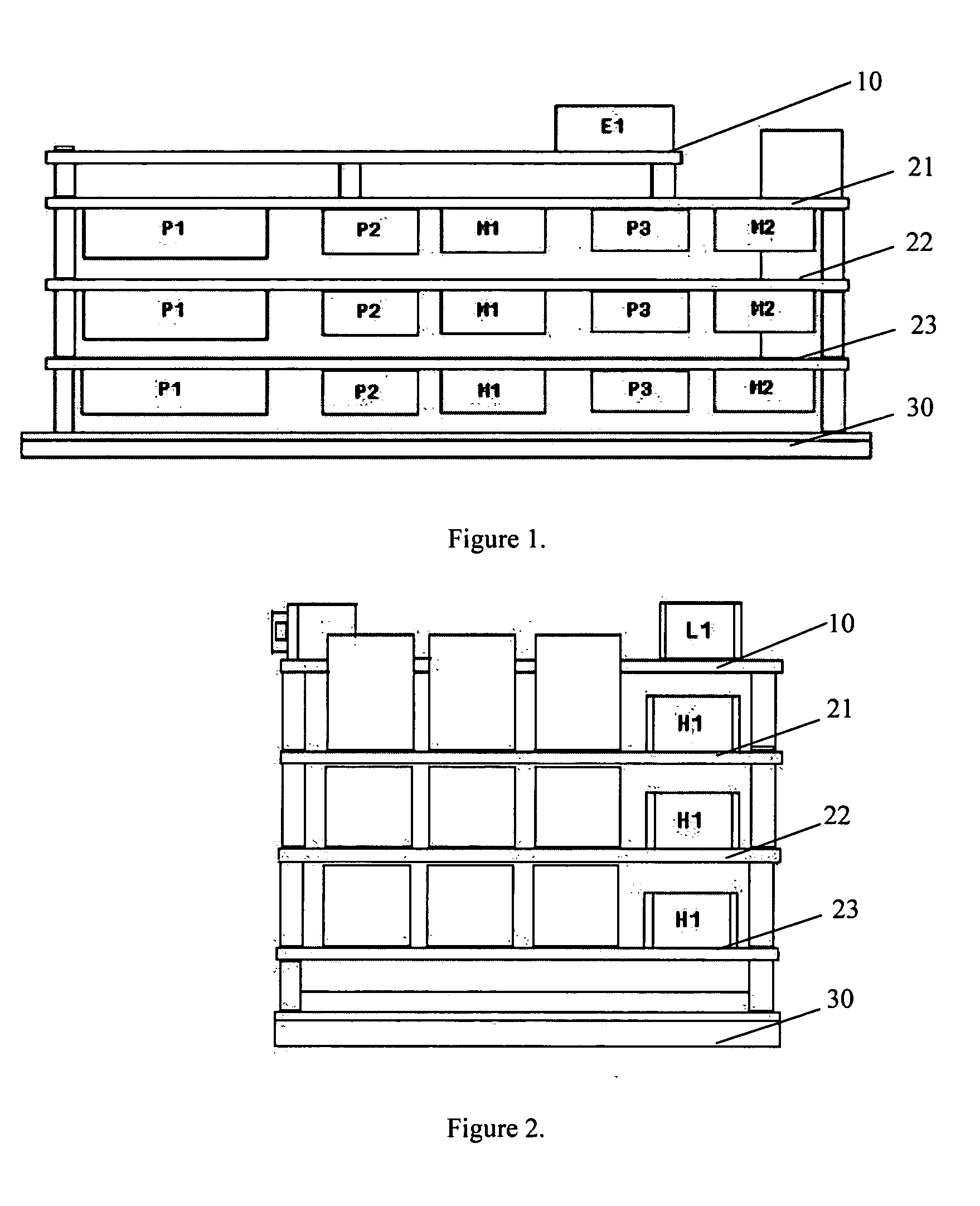
[0039]FIG. 1 is front view of the modular multi-axis motion control & driving system according to the embodiment of the present invention. As illustrated in FIG. 1, the toppest layer is a control board (a four layer PCB) 10, others layers are driver board 21, 22 and 23 (a six layer PCB), the bottom layer is a heat sink board 30. The dimension of the entire system is 170×100×75.

[0040] The modular multi-axis motion control and driving system of the embodiments of this invention consists of one control board 10 and several driver boards 21, 22 and 23. The number of driver boards is one to three. Each driver board can drive two motors (DC brushless, DC brushed or AC servo motor). The multi-axis motion control system can be implemented by using one control board and several driver boards. Therefore, a 4-axis system can be established using one control board and two driver boards, and a 6-axis system can be established using one control board and three driver boards.

[0041] The embodimen...


PUM


Abstract

A modular multi-axis motion control and driving system is developed by using advanced Digital Signal Processor (DSP) and Field Programmable Gate Array (FPGA) technologies. A modular multi-axis motion control and driving system comprises: a control board comprising a DSP and Flash ROM connected to each other, for performing position control and current control of said system; a plurality of driver boards, connected to the control board through a bus, each of which comprise a FPGA device and a plurality of MOSFET power amplifier, for driving a plurality of servo motors; a computer, connected to said control board, for providing graphic user interface, through which motor setting, current and position loop tuning and diagnostic can be performed; Wherein, a control program, system parameters and FPGA configuration file are stored in said Flash ROM, when the system power is on, the DSP automatically executes an loader firmware to transfer the control program from said Flash ROM to the memory of DSP for execution, then the DSP reads the FPGA configuration file from the Flash ROM and configure the FPGA in the driver board, after that, the control program runs into a circulation loop to do system diagnose, network service and check command queue, while the current and position controls are implemented in an interrupt service.

Description

TECHNICAL FIELD [0001] This invention relates to the digital control and power electronic technologies. More specifically, to a universal multi-axis digitized motion control & driving system and the method thereof that can be used in many different applications. BACKGROUND OF THE INVENTION [0002] As a core technology in modern manufacturing, advanced motion control systems have received considerable attention in the past decades. Motion control is a fundamental concern in many industrial applications. For example, putting an object in the correct place with the right amount of force at the right time is essential for efficient manufacturing operations. High speed and high accuracy positioning systems are essential elements in advanced manufacturing systems such as semiconductor industry (e.g. Surface Mounting Technology-SMT). The demands for higher productivity and quality call for the development of high performance positioning devices. Motion control is widely used in modern manuf...

Claims


Application Information

Patent Timeline
Patent Type & Authority Applications(United States)
IPC IPC(8): G05B19/18
CPCG05B19/4141G05B2219/34024G05B2219/34047G05B2219/34157G05B2219/34466G05B2219/36386G05B2219/50216
Inventor SUN, DONGSHAO, XIANYIN
Owner DYNACITY TECH HK
Learn More