Dual linear ultrasound control

a technology of ultrasound control and linear motion, which is applied in the field of ophthalmic surgical control systems, can solve the problems of unfavorable surgery, unfavorable surgery, and inability of the foot controller to independently control more than one of these parameters

Inactive Publication Date: 2008-05-15
BAUSCH & LOMB INC
View PDF6 Cites 127 Cited by
  • Summary
  • Abstract
  • Description
  • Claims
  • Application Information

AI Technical Summary

Problems solved by technology

Prior art systems did not allow the foot controller to independently control more that one of these parameters at a time.
This could lead to unwanted delay in the surgery.

Method used


Image

  • Dual linear ultrasound control
  • Dual linear ultrasound control
  • Dual linear ultrasound control

Examples


Embodiment Construction

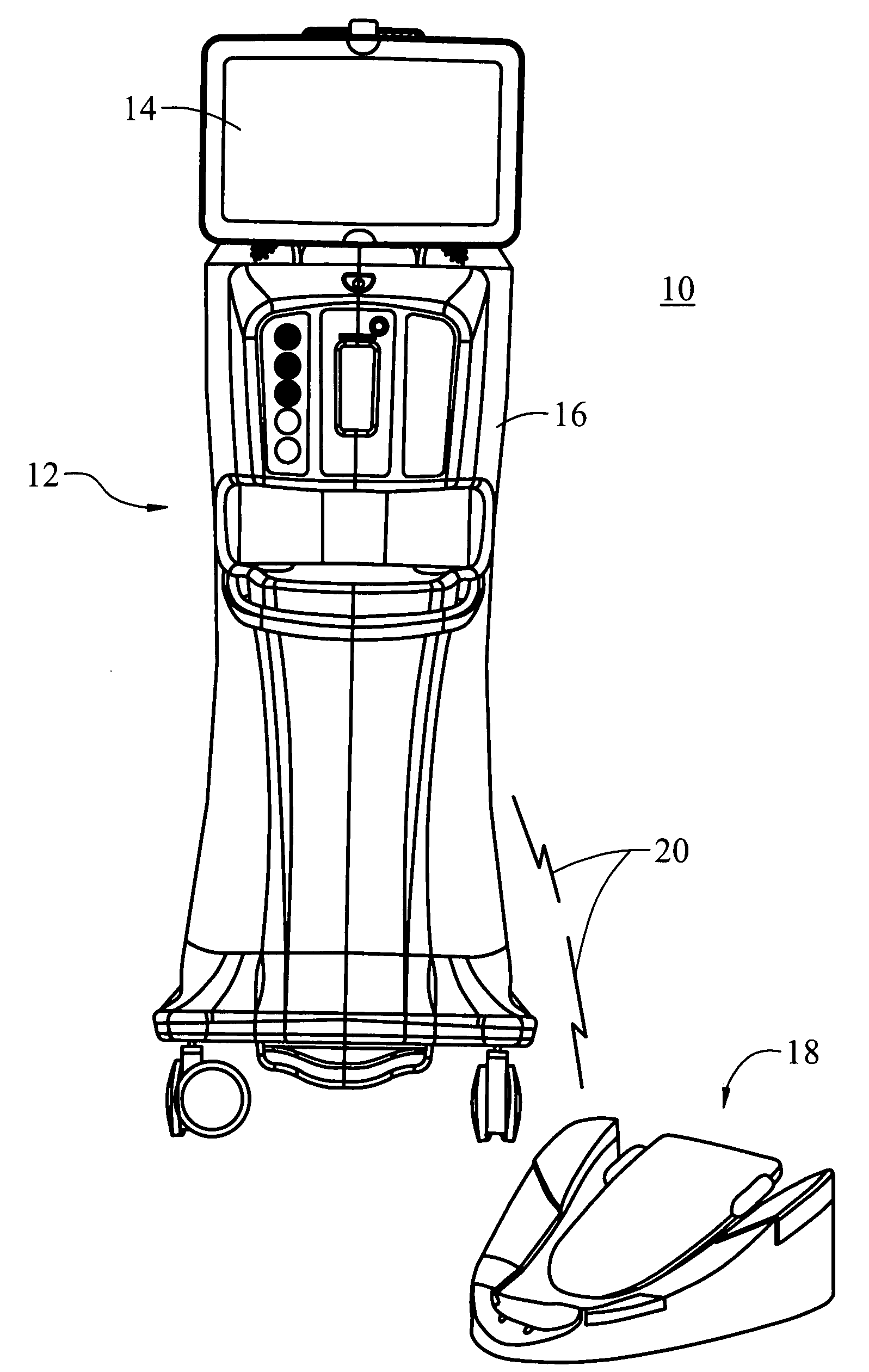
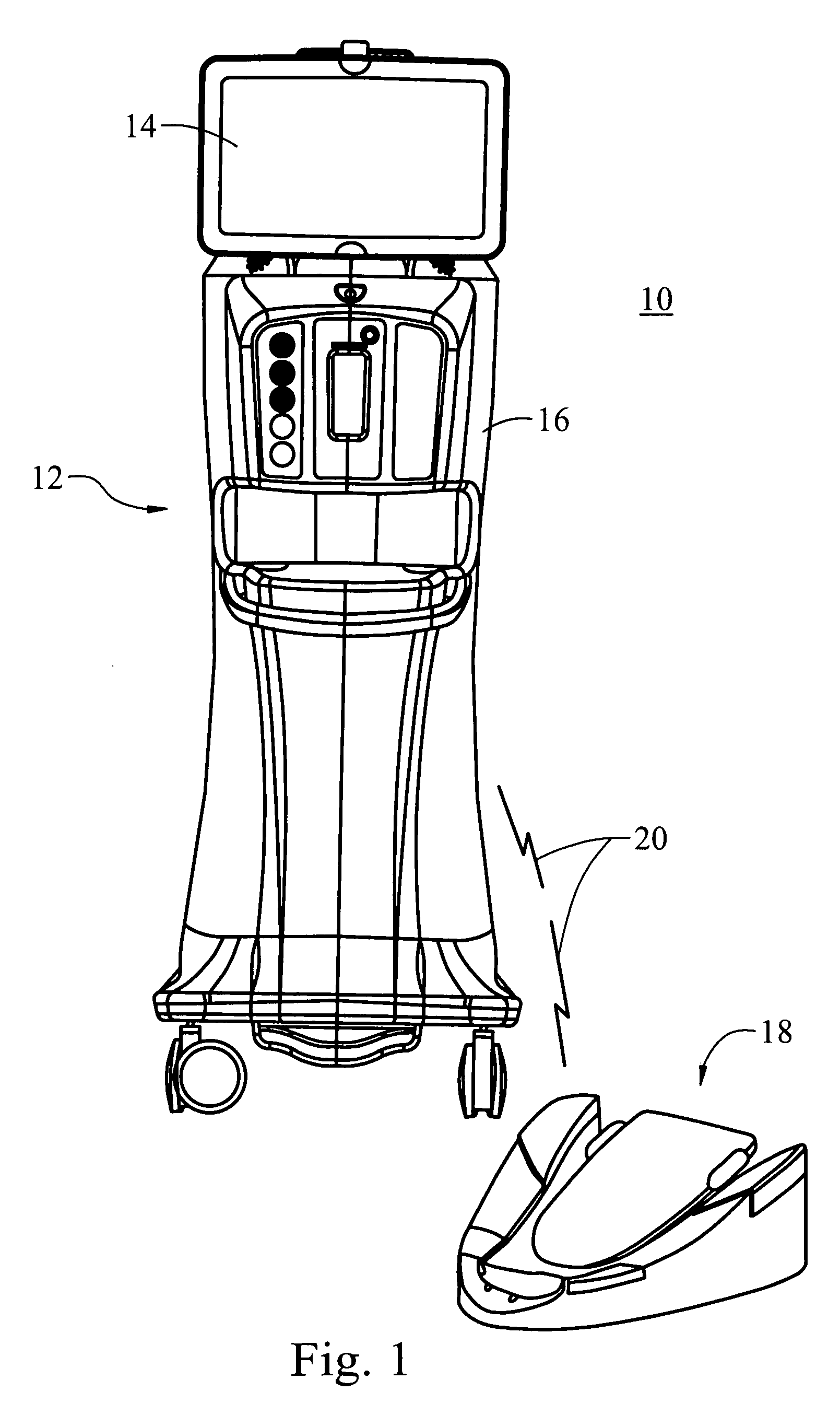
[0010]FIG. 1 shows an ophthalmic surgical control system 10 in accordance with the present invention. System 10 includes a surgical console 12 with a display 14 and control modules (not shown) within body 16. The system 10 is also connected to a foot controller 18 for movement of a pedal by a user over a pre-determined range in pitch and yaw. Foot controller 18 may be connected to the console 12 by a cable or wirelessly as indicated by lines 20. Surgical console 12 controls a variety of surgical instruments. The system 10 allows the foot controller 18 to independently control two parameters for a single function where a first parameter is controlled by movement of the pedal in pitch and a second parameter is controlled by movement of the pedal in yaw.

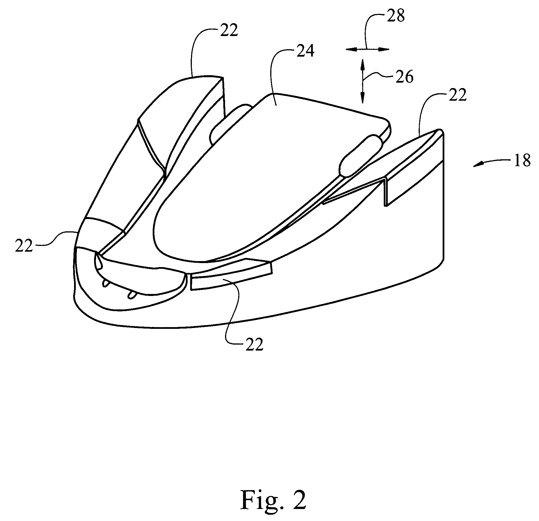
[0011]The foot controller 18, best seen in FIG. 2, typically has four buttons 22 and a center foot pedal 24, which has two axes of movement, to control two linear functions simultaneously or two parameters of a single function independe...


PUM


Abstract

An ophthalmic surgical control system 10 includes a surgical console 12 for controlling a variety of surgical instruments. A foot controller 18 is connected to the surgical console 12 including a pedal 24 for movement by a user over a pre-determined range in pitch 26 and yaw 28. The system 10 allows the foot controller 18 to independently control two parameters for a single function where a first parameter is controlled by movement of the pedal 24 in pitch 26 and a second parameter is controlled by movement of the pedal 24 in yaw 28.

Description

BACKGROUND OF THE INVENTION [0001]1. Field of the Invention[0002]The present invention is related to ophthalmic surgical control systems having foot controllers and, more particularly, to foot controllers having foot pedals with movement in both pitch and yaw.[0003]2. Description of Related Art[0004]The use of foot controllers in ophthalmic surgical systems is well known. The foot controllers typically have a foot pedal that pivots about an axis. As the pedal is depressed the foot controller causes a change in some operating function such as ultrasound, irrigation and aspiration, vitrectomy cutter, coagulation, or some other function. The movement or travel in pitch, i.e. up and down, of the pedal is typically divided into one or more regions. For example a total pitch movement of the pedal may be 15° with three regions contained within the 15° of movement. Continuing with the three region example, each region then forms some portion of the total 15° of movement. For example region ...

Claims


Application Information

Patent Timeline
Patent Type & Authority Applications(United States)
IPC IPC(8): A61F9/007
CPCA61B2017/00181A61B2017/00199A61B2017/00221A61B2017/00446A61M1/008A61B2017/00977A61B2019/2292A61F9/00745A61B2017/00973A61B34/76
Inventor HERTWECK, DAVID W.KNIGHT, JEFFERY A.
Owner BAUSCH & LOMB INC
Why Eureka
Try Eureka