Pile driving control apparatus and pile driving system

a control apparatus and pile technology, applied in the direction of bulkheads/piles, material strength using repeated/pulsating forces, portable percussive tools, etc., can solve the problems of high impact energy required to drive a pile into the ground, deformation and energy dissipation, heat and sound, etc., to reduce the impact velocity of the hammer

Active Publication Date: 2008-07-29
BERMINGHAM FOUND SOLUTIONS LTD
View PDF21 Cites 813 Cited by
  • Summary
  • Abstract
  • Description
  • Claims
  • Application Information

AI Technical Summary

Benefits of technology

[0025]In some embodiments, the controller is further operable to provide the control signal by comparing the determined vibration to a maximum allowable vibration, and generating, as the control signal, a control signal to cause the hydraulic control system to adjust the throttle so as to reduce the impact velocity of the hammer for the subsequent hammer stroke based on the comparison.

Problems solved by technology

Driving a pile into the ground requires high impact energy to overcome soil resistance.
However, not all of this kinetic energy is transferred to the pile because of the inelasticity of the collision, which results in deformation and energy dissipation in the form of heat and sound.
One of the main recurrent problems in pile driving is controlling the impact of the hammer on the pile.
If the impact energy is too little, the pile does not penetrate the soil and time and energy is lost.
If the impact energy is too great, the pile may be damaged or broken.
Indeed, concrete piles are susceptible to cracking if the impact stresses are too large.
However, the dynamic formulae are intrinsically inaccurate because the dynamic modeling of the hammer, driving system, pile and soil is based on simplifications and assumptions that do not always simulate reality.
Even if dynamic models were further refined, they would still not be able to account for the fact that soil conditions may vary with depth or may change due to repetitive impacting.
However, certain drawbacks are evident from the prior art designs.
The manual control of impact energy is both time-consuming and inaccurate.
The types of parameters that can be used to control pile driving also tend to be limited.

Method used


Image

  • Pile driving control apparatus and pile driving system
  • Pile driving control apparatus and pile driving system
  • Pile driving control apparatus and pile driving system

Examples


Embodiment Construction

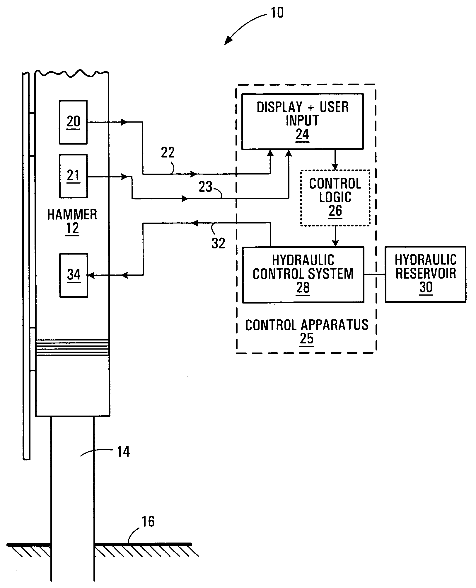
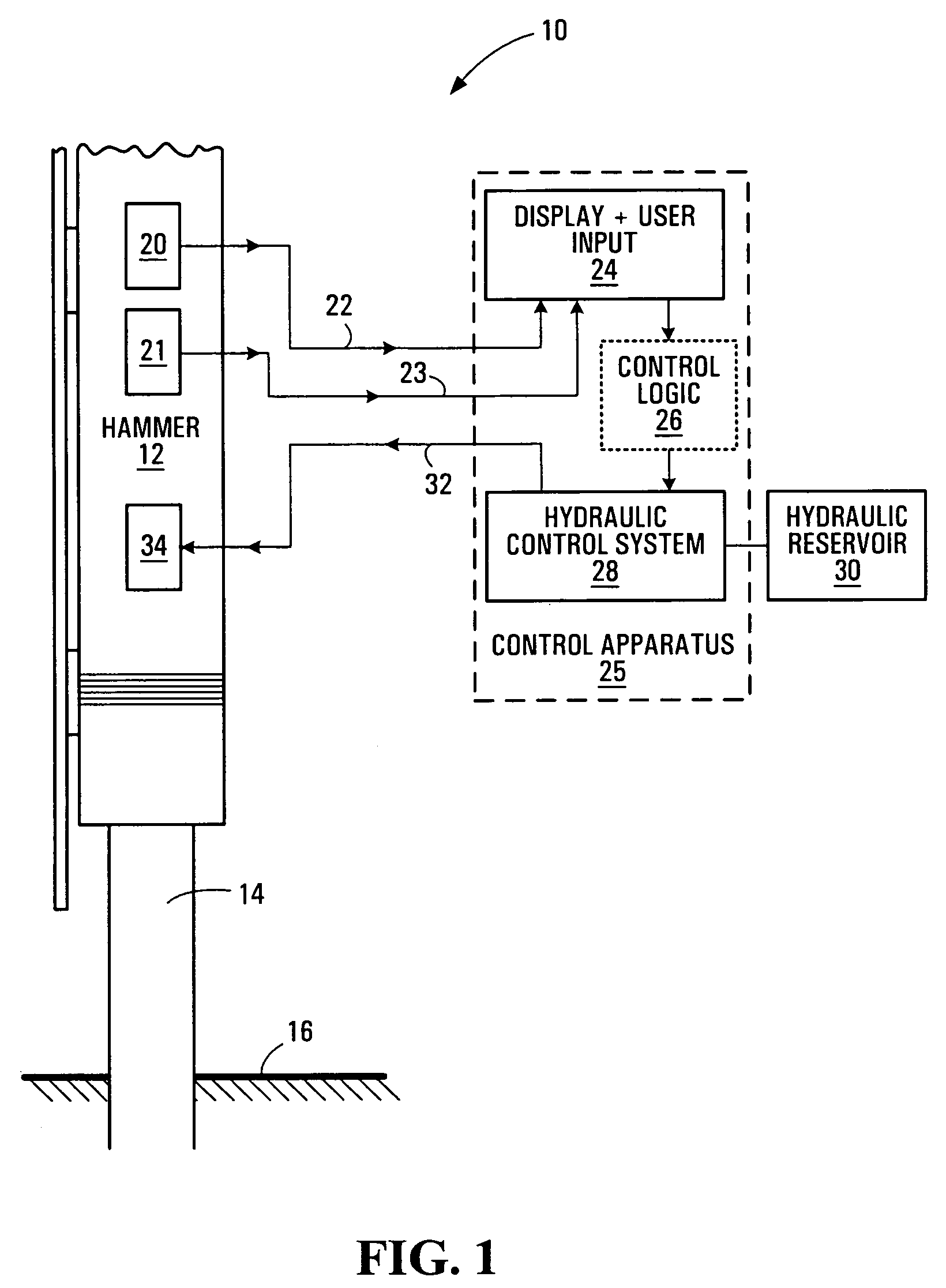
[0037]Referring to FIG. 1, a pile driving system or apparatus 10, also referred to herein as a pile driver, comprises a hammer 12, also known as a ram, which is used to impact the top of a pile 14 so as to drive the pile 14 into the ground 16. In one embodiment, the pile driver 10 is a diesel pile driver. It should be appreciated that embodiments of the present invention can be applied to other types of pile drivers, such as hydraulic pile drivers, pneumatic pile drivers and drop hammers.

[0038]Located on the hammer 12 is a velocity sensor 20 that is capable of measuring the velocity of the hammer 12 just before it impacts the pile 14. The velocity sensor 20 may include two magnetic proximity switches (not shown). The pair of magnetic proximity switches may be located, for example, on the side of the hammer 12. In one embodiment, the proximity switches are set to close approximately 1 inch above impact. The time elapsed between the closing of the magnetic proximity switches is transd...


PUM

PropertyMeasurementUnit
velocityaaaaaaaaaa
impact velocityaaaaaaaaaa
velocity sensoraaaaaaaaaa

Abstract

A pile driving control apparatus for a pile driving system includes a hydraulic control system that controls a throttle of a pile driving hammer, and thereby controls an impact velocity of the hammer with a pile. A controller provides a control signal to the hydraulic control system. Based on the control signal, the hydraulic control system controls an impact velocity of the hammer during a subsequent hammer stroke. The controller may determine one or more control parameters such as sound pressure at a sound control location during a hammer stroke, vibration at a vibration control location during a hammer stroke, an impact force imparted to the pile during a hammer stroke, and / or actual pile capacity of the pile, and provide to the hydraulic control system a control signal based on the determined control parameter(s).

Description

CROSS-REFERENCE TO RELATED APPLICATIONS[0001]This application claims the benefit of, and is a continuation-in-part of, U.S. patent application Ser. No. 10 / 843,664, which was filed on May 12, 2004, now U.S. Pat. No. 7,156,188 claiming the benefit of U.S. Provisional Patent Application Ser. No. 60 / 469,415, filed on May 12, 2003.[0002]The entire contents of each of these related patent applications is incorporated herein by reference.FIELD OF THE INVENTION[0003]This invention relates to pile drivers and, more particularly, to pile drivers with control systems.BACKGROUND[0004]Pile drivers are used in the construction industry to drive piles, also known as posts, into the ground. Piles are used to support massive structures such as bridges, towers, dams and skyscrapers. Piles, or posts, may be made of timber, steel, concrete or composites. Driving a pile into the ground requires high impact energy to overcome soil resistance. However, the impact energy must not be so large as to damage t...

Claims


Application Information

Patent Timeline
Patent Type & Authority Patents(United States)
IPC IPC(8): E02D13/00B25D1/00E02D7/02E02D13/06
CPCE02D13/06E02D7/02
Inventor BERMINGHAM, PATRICK DONALDTRISKA, MARKJUSTASON, MICHAELHOOVER, DAVIDGABALDO, STEFANOMIDDENDORP, PETERCODD, WILLIAM
Owner BERMINGHAM FOUND SOLUTIONS LTD
Why Eureka
Try Eureka