Method for operating a fuel injection system of an internal combustion engine

Active Publication Date: 2015-09-01
ROBERT BOSCH GMBH
View PDF34 Cites 5 Cited by
  • Summary
  • Abstract
  • Description
  • Claims
  • Application Information

AI Technical Summary

Benefits of technology

[0004]Example embodiments of the present invention provide a method for operating a fuel injection system of an

Problems solved by technology

In the case of a currentless, open quantity control valve, for example, this is based on the idea that when the current feed of the electromagnetic operating device in the adaptation method has dropped to the extent that the quantity control valve is no longer closing, there will be a pressure

Method used


Image

  • Method for operating a fuel injection system of an internal combustion engine
  • Method for operating a fuel injection system of an internal combustion engine
  • Method for operating a fuel injection system of an internal combustion engine

Examples


Example

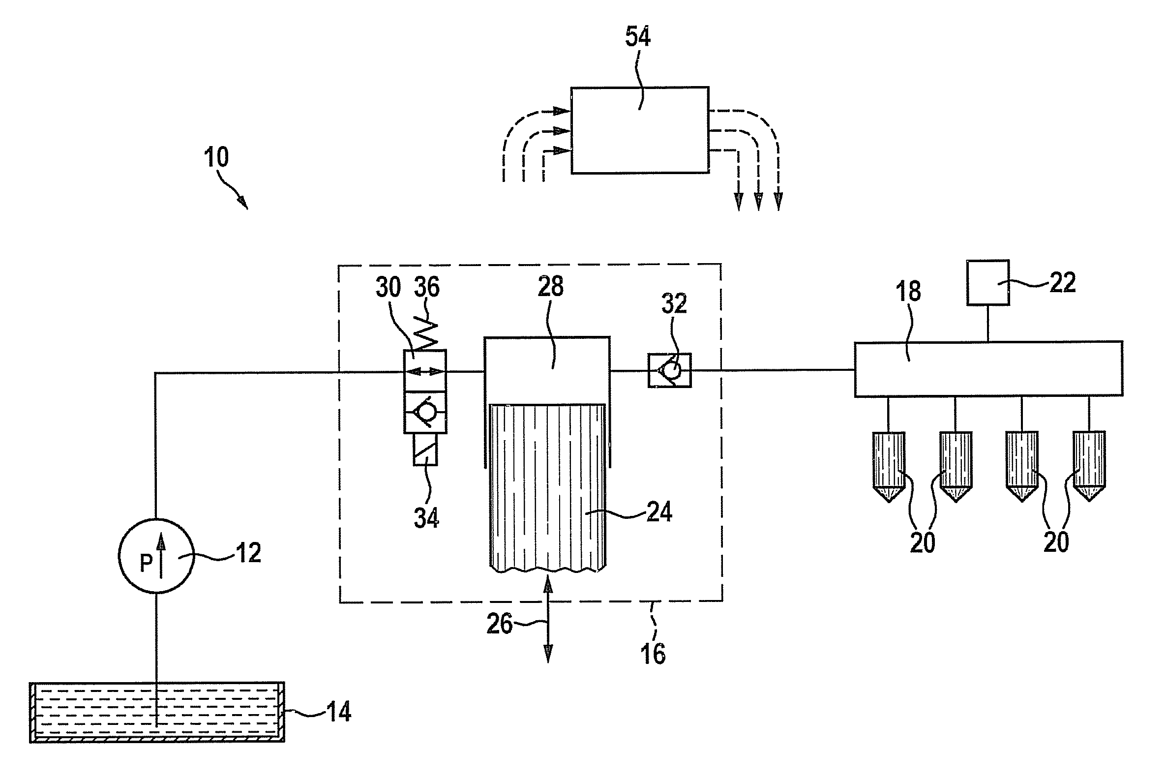
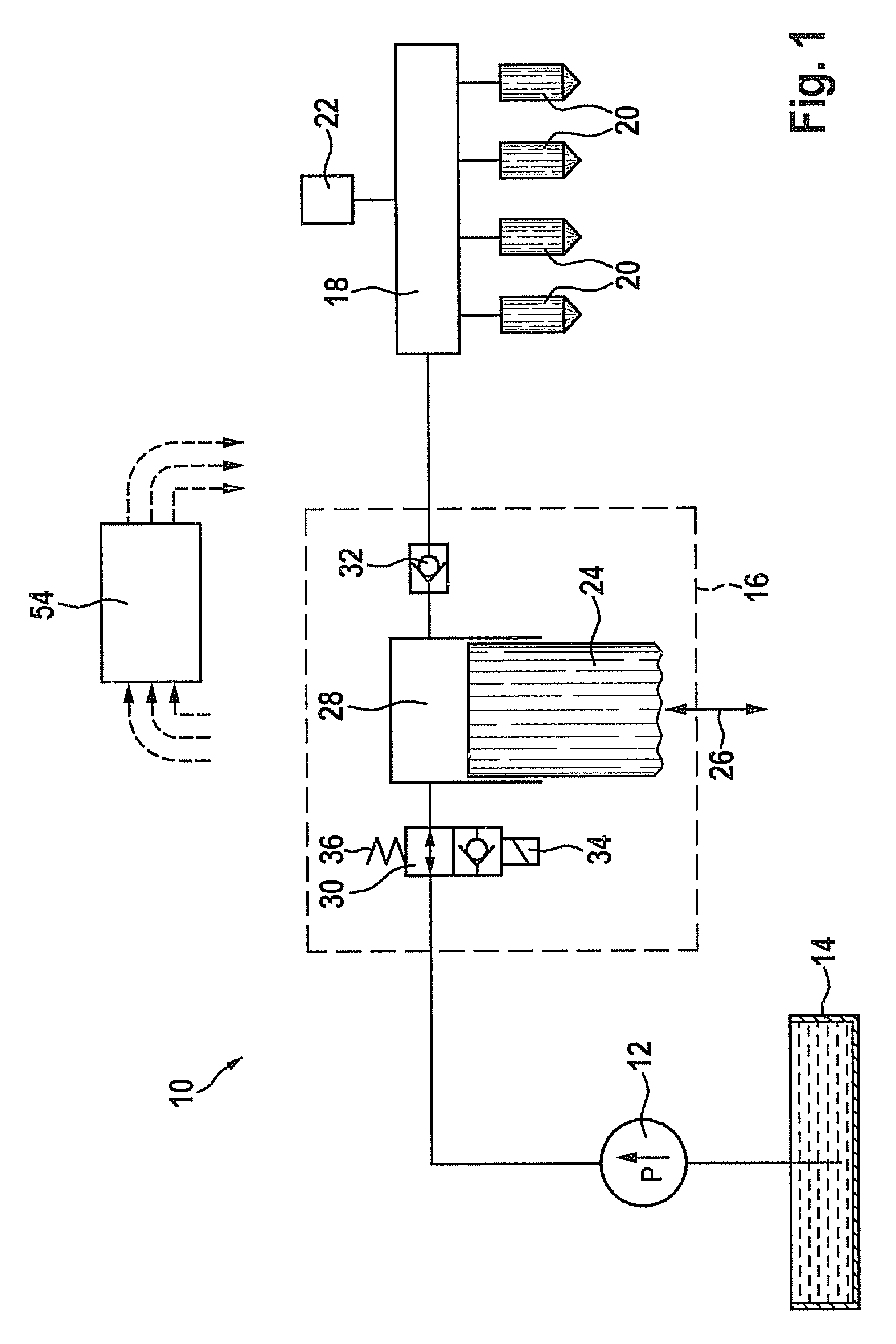
[0024]A fuel injection system in FIG. 1 is labeled overall using reference numeral 10. It includes an electrical fuel pump 12, using which fuel is delivered from a fuel tank 14 to a high-pressure pump 16. High-pressure pump 16 compresses the fuel to a very high pressure and delivers it further into a fuel rail 18. A plurality of injectors 20 is connected to this fuel rail, injecting fuel into combustion chambers assigned to the injectors. The pressure in fuel rail 18 is detected by a pressure sensor 22.

[0025]High-pressure pump 16 is a piston pump having a delivery piston 24, which may be induced to move back and forth (double arrow 26) by a camshaft (not shown). Delivery piston 24 delimits a delivery chamber 28 which may be connected via a quantity control valve 30 to the outlet of electrical fuel pump 12. Delivery chamber 28 may also be connected to fuel rail 18 via an outlet valve 32.

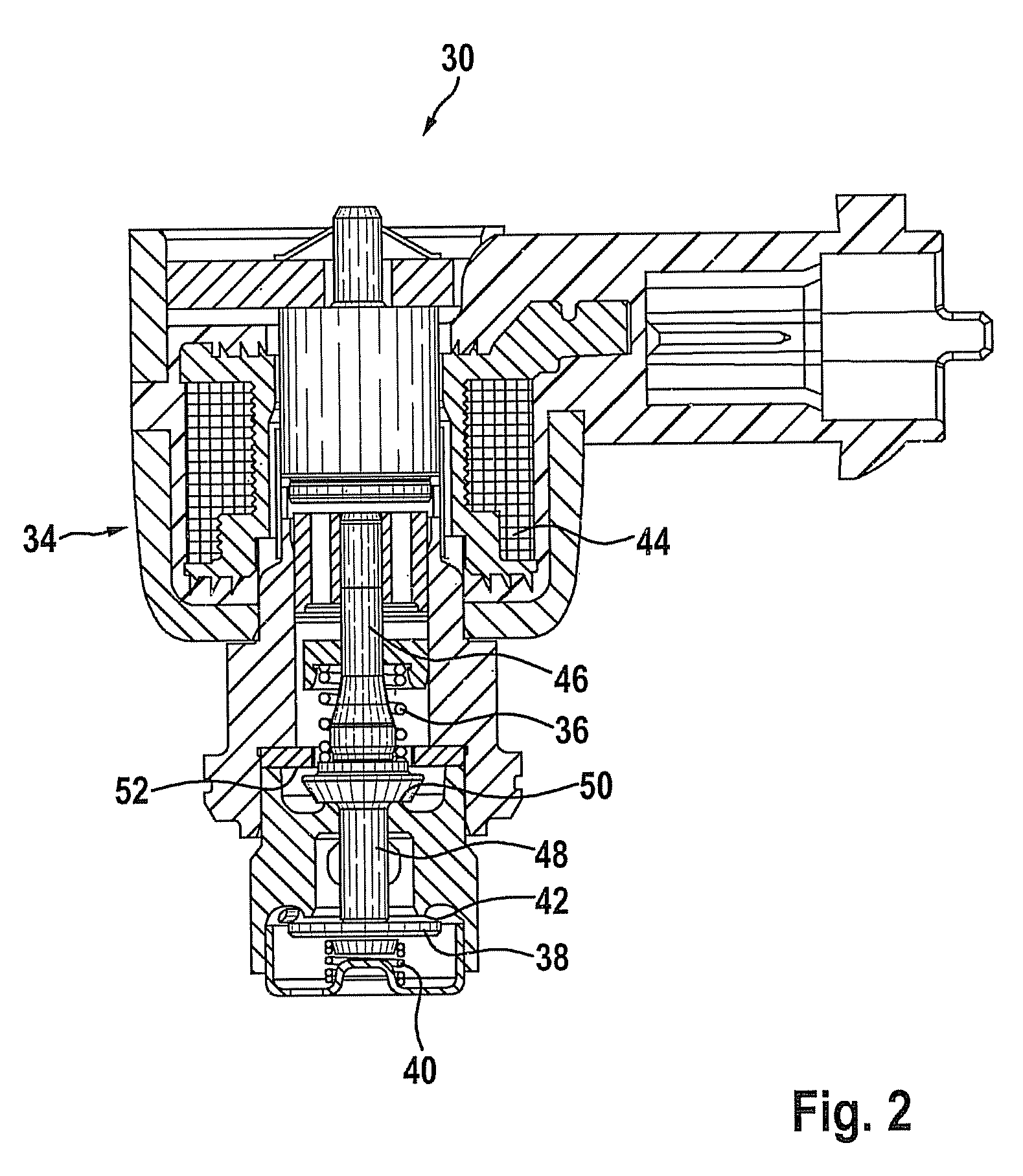
[0026]Quantity control valve 30 includes an electromagnetic operating device 34, which in the ener...


PUM


Abstract

In a fuel injection system of an internal combustion engine fuel is delivered into a fuel rail by a high-pressure pump. The quantity of the delivered fuel is influenced by a quantity control valve operated by an electromagnetic operating device. At least one parameter of a braking pulse of the electromagnetic actuating device depends on an efficiency of the electromagnetic actuating device and/or on a supply voltage of a voltage source and/or on a temperature, in particular of a component of the fuel injection system or of the internal combustion engine.

Description

FIELD OF THE INVENTION[0001]The present invention relates to a method for operating a fuel system of an internal combustion engine and to a computer program and an electrical memory medium as well as a control and regulating unit.BACKGROUND INFORMATION[0002]DE 101 48 218 describes a method for operating a fuel injection system using a quantity control valve. The known quantity control valve is implemented as a solenoid valve which is operated electromagnetically by a solenoid and has a magnetic armature and corresponding path-limiting stops. The known solenoid valve is open in the energized state of the coil. However, such quantity control valves, which are closed in the currentless state of the solenoid, are also known from the market. In the latter case the solenoid is triggered using a constant voltage or a clocked voltage (pulse width modulation, “PWM”) to open the quantity control valve so that the current in the solenoid increases in a characteristic manner. After switching of...

Claims


Application Information

Patent Timeline
IPC IPC(8): F02D41/38F02M69/50F02D41/20F02D41/24F02D41/34F02D41/40
CPCF02D41/20F02D41/2464F02D41/345F02D41/3845F02D41/401F02D2041/2027F02D2041/2037F02D2041/2055F02D2200/0602
Inventor RICHTER, UWEWILMS, RAINERSCHUMACHER, MATTHIASKUEMPEL, JOERGMAESS, MATTHIAS
Owner ROBERT BOSCH GMBH
Why Eureka
Try Eureka