
Shedding apparatus for a weaving machine, in particular for a ribbon weaving machine

a technology of shedding apparatus and weaving machine, which is applied in the direction of cam shedding mechanism, dollies, textiles and paper, etc., can solve the problems of occupying a relatively large space and complicated control of holding devi

Inactive Publication Date: 2009-11-12
TEXTILMA AG
View PDF16 Cites 6 Cited by
  • Summary
  • Abstract
  • Description
  • Claims
  • Application Information

AI Technical Summary

Benefits of technology

[0007]It is advantageous if at least 75% of the kinetic energy is taken from the tension / compression spring, and the linear motor provides at most 25% of the kinetic energy.
[0009]A form is particularly advantageous, since the entry of the magnetically acting holding elements, which are advantageously formed from iron, into the effective range of the coil magnets avoids direct contact, resulting in particularly low-noise running of the shedding apparatus.
[0011]It is particularly advantageous with respect to the allocation of space and the dynamic properties of the system if the tension / compression spring is formed as a leaf spring, and thereby formed in an ring-like manner. It goes without saying that in this context a ring does not have to be interpreted as a circular formation. Rather, the term “ring-like” is to be understood as meaning closed formations such as round, oval, elliptical or similarly formed springs, which are possibly suitable for accommodating components within them for the purpose of reducing the space requirement. In one particular embodiment, it is provided that the spring force to be applied is divided between two springs, which are arranged at the ends of the heddle apparatus. In order to eliminate the transverse forces, it is advantageous if the heddle apparatus is formed symmetrically with respect to its center axis.
[0014]It is advantageous if the linear motor has a flat coil, which is arranged in the plane of the heddle frame.

Problems solved by technology

However, the configuration with the two springs of WO-A-98 / 24955 takes up a relatively large space, as the drawings there also show.
Furthermore, the controlled holding device is complicated, even if it takes the form of permanent magnets, because of the electromagnetic influence on the permanent magnets.

Method used


Image

  • Shedding apparatus for a weaving machine, in particular for a ribbon weaving machine
  • Shedding apparatus for a weaving machine, in particular for a ribbon weaving machine
  • Shedding apparatus for a weaving machine, in particular for a ribbon weaving machine

Examples


Embodiment Construction

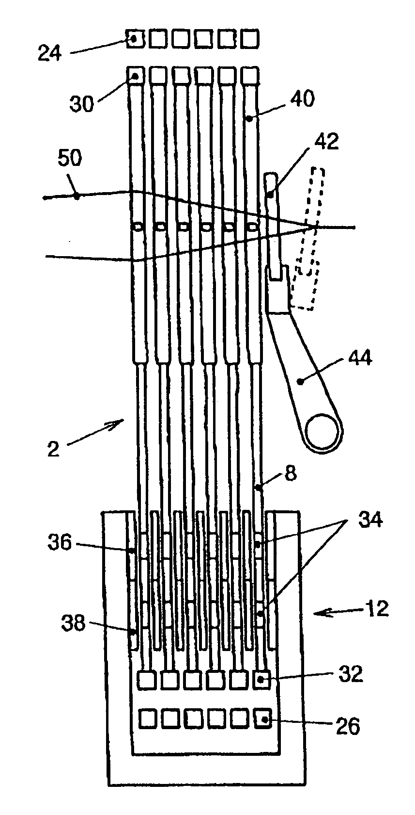
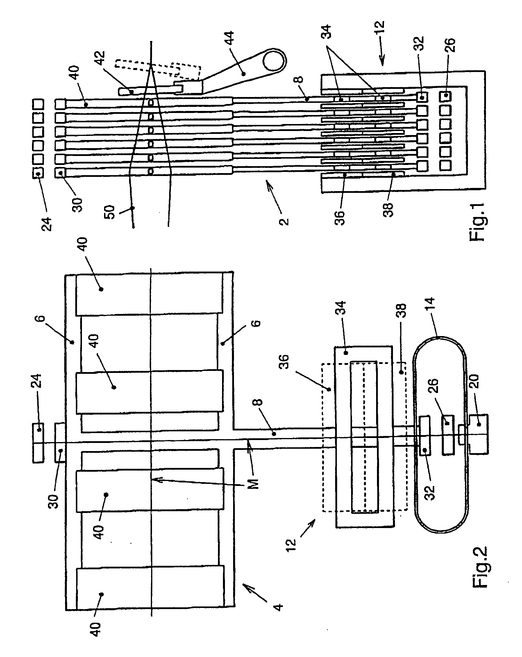
[0024]A first exemplary embodiment for carrying out the present invention is represented in FIGS. 1 and 2.

[0025]FIG. 1 shows the diagram of the weaving region of a weaving machine in side view. A shedding apparatus with a number of heddle apparatuses 2 serves the purpose of opening warp threads 50 to form a weaving shed with an upper shed and a lower shed, into which a weft insertion element inserts a weft thread with every change of shed. A weaving reed 42 beats up the inserted weft thread at the edge of the fabric produced.

[0026]As FIG. 2 reveals, each heddle apparatus 2 includes a heddle frame 4, with heddle supports 6, on which heddles 40 for guiding the warp threads 50 are arranged. In the present example, the heddles 40 are grouped together in four groups for four weaving locations of a ribbon weaving machine. The heddle frame 4 is connected to a linear motor 12 by way of a heddle connector 8. In FIG. 1, the heddle apparatus 2 has at the top and bottom and upper, fixed stop ma...


PUM


Abstract

In order to make a small space requirement, a low energy requirement and therefore an increased weaving frequency possible in a shedding apparatus, a spring drive is proposed which is connected to magnetically acting holding means. The holding means are capable of holding the heddle frame in an upper shed position and in a lower shed position counter to the spring force. Furthermore, the heddle frame is connected to a linear motor. A heddle movement can be initiated by said linear motor. According to the invention, the spring drive is configured as a tension / compression spring which is designed in such a way that, during operation of the heddle frame at the resonant frequency of the spring drive the greater part of the kinetic energy can be obtained from the spring drive.

Description

[0001]This application claims priority of PCT application PCT / CH2007 / 000475 having a priority date of Sep. 28, 2006, the disclosure of which is incorporated herein by reference.TECHNICAL FIELD[0002]The invention relates to a shedding apparatus for a weaving machine, in particular for a ribbon weaving machine.BACKGROUND OF THE INVENTION[0003]Shedding apparatuses for weaving machines which have a heddle apparatus and a heddle frame are known in principle from numerous documents. WO-A-98 / 24955 discloses a weaving machine in which the dragging element for dragging the warp threads of a weaving machine and comprising for example a heddle frame is clamped between two springs. There, the dragging element oscillates and a holding device is capable of stopping the oscillation for a certain time, and so forming a shed during the weft insertion. The holding device from WO-A-98 / 24955 is intended to be controllable by means of a control unit. Permanent magnets which can be influenced by electrom...

Claims


Application Information

Patent Timeline
IPC IPC(8): D03C13/00D03C15/00D03C1/00
CPCD03C1/00D03C13/025D03C13/00D03C5/00
Inventor BORER, SILVAN
Owner TEXTILMA AG
Learn More