Cutter Head For Personal Care Appliances

Inactive Publication Date: 2017-12-28
BRAUN GMBH
View PDF9 Cites 6 Cited by
  • Summary
  • Abstract
  • Description
  • Claims
  • Application Information

AI Technical Summary

Benefits of technology

[0007]It is an objective underlying the present invention to provide for an improved personal care appliance and an improved tool head for such personal care appliance avoiding at least one of the disadvantages of the prior art and/or further developing the existing solutions. A more particular objective underlying the invention is to provide for an improved transmission architecture for transmitting the drive unit's action to the plurality of tooling rotors, wherein noise emissions from the drive

Problems solved by technology

However, the higher the number of cutting rotors in the cutter head, the more complex the drive train and the higher the number of drive train elements.
This may cause problems with accommodating the drive train elements in the cutter head which should have a small size to allow for easy handling of th

Method used


Image

  • Cutter Head For Personal Care Appliances
  • Cutter Head For Personal Care Appliances
  • Cutter Head For Personal Care Appliances

Examples


Embodiment Construction

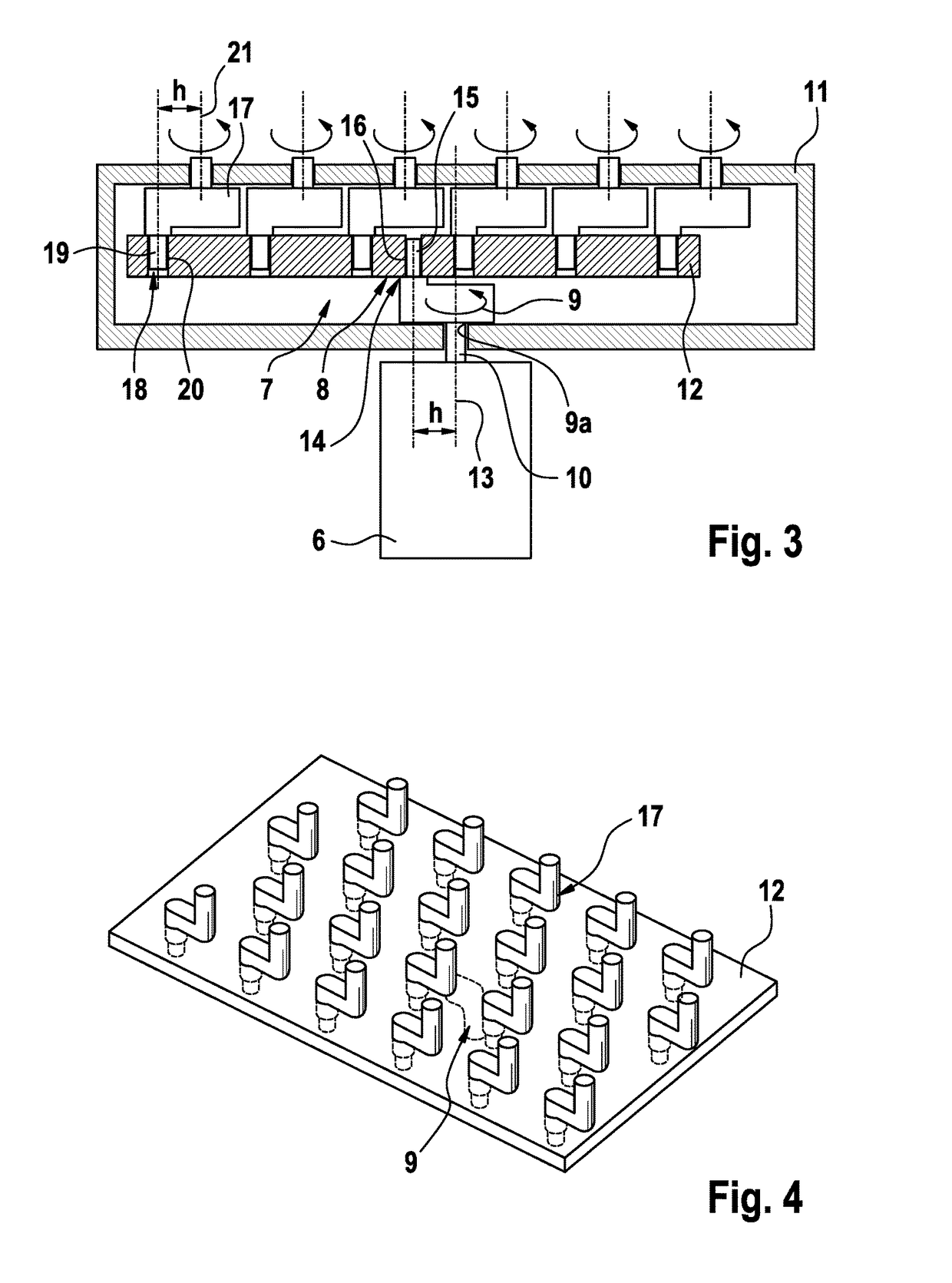
[0018]In order to transmit the driving action of a drive shaft which may be the motor shaft of an electric motor or may be connected thereto by means of intermediate transmission elements, to a plurality of tooling rotors in the tooling head of a personal care appliance, the drive train connecting said drive shaft to the plurality of tooling rotors and distributing the driving torque of the drive shaft to each of the plurality of tooling rotors includes a crank mechanism comprising an input crank element having connection means for connecting to said drive shaft, a transmitter element configured to be driven by said input crank element and a plurality of output crank elements configured to be driven by said transmitter element to rotate about the rotor axes of said plurality of tooling rotors. Said tooling rotors may be connected to the rotating portions of the output crank elements in a torque-transmitting way. The input crank element may transform the rotation of the drive shaft i...


PUM


Abstract

The present invention relates a tool head for a personal care appliance, including a plurality of tool rotors rotatably supported about rotor axes and a drive train for rotatably driving said tooling rotors from a motor, wherein such drive train includes: an input crank element having connection means for connecting to a drive shaft, a transmitter element configured to be driven by said input crank element, and output crank elements configured to be driven by said transmitter element to rotate about said rotor axis.

Description

FIELD OF THE INVENTION[0001]The present invention relates to personal care appliances such as shavers, hair removal devices, skin peeling devices or toothbrushes having tools of the rotatory type. More particularly, the invention relates to a tool head for a personal care appliance, including a plurality of tooling rotors rotatably supported about rotor axes and a drive train for rotatorily driving said tooling rotors from a motor. The invention also relates to an electric shaver having a cutter head with a plurality of cutting rotors driven by a drive train connectable to a motor.BACKGROUND OF THE INVENTION[0002]Electric shavers may have one or more rotatory cutter elements which may be driven in an oscillating or a continuous manner by an electric motor connected to the rotatory cutter elements through a drive train transmitting the rotation of the motor shaft to the rotatory cutter elements.[0003]In cutter heads having a plurality of cutting rotors, the driving motion of the moto...

Claims


Application Information

Patent Timeline
IPC IPC(8): B26B19/28B26B19/14B26B19/38
CPCB26B19/282B26B19/141B26B19/3846B26B19/3853B26B19/386B26B19/14B26B19/28B26B19/3886
Inventor SCHUEBEL, CHRISTIANKLUGE, MARTINFUELLGRABE, MARTINSTAUB, ANDREASLAUBER, ANDREASENZLER, AUGUSTCURTIS, RAYMOND
Owner BRAUN GMBH
Why Eureka
Try Eureka