Tapered sound outlet vane pump

a vane cell pump and sound outlet technology, which is applied in the direction of rotary/oscillating piston pump components, machines/engines, liquid fuel engines, etc., can solve the problems of noticeable output throttling negative effect of the preliminary sound-damping outlet on the output of the vane cell pump, etc., and achieve low-noise operation

Active Publication Date: 2013-02-21
HELLA KG HUECK & CO
View PDF5 Cites 6 Cited by
  • Summary
  • Abstract
  • Description
  • Claims
  • Application Information

AI Technical Summary

Benefits of technology

[0007]The present invention addresses this problem and sets itself the task of disclosing a vane cell pump of the type named above, which makes low-noise operation possible without the associated output throttling.

Problems solved by technology

It has been shown that such a construction of the preliminary sound-damping outlet has a negative effect on the output of the vane cell pump.
The geometry of the preliminary sound-damping outlet with a cross-sectional jump from a large flow cross section to a small flow cross section caused by the slot-shaped construction of the preliminary sound-damping outlet leads to noticeable output throttling of the vane cell pump.

Method used


Image

  • Tapered sound outlet vane pump
  • Tapered sound outlet vane pump
  • Tapered sound outlet vane pump

Examples


Embodiment Construction

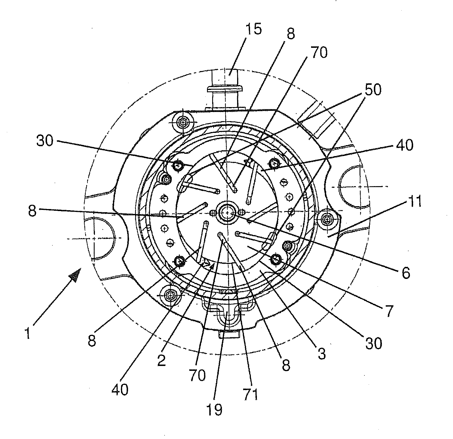
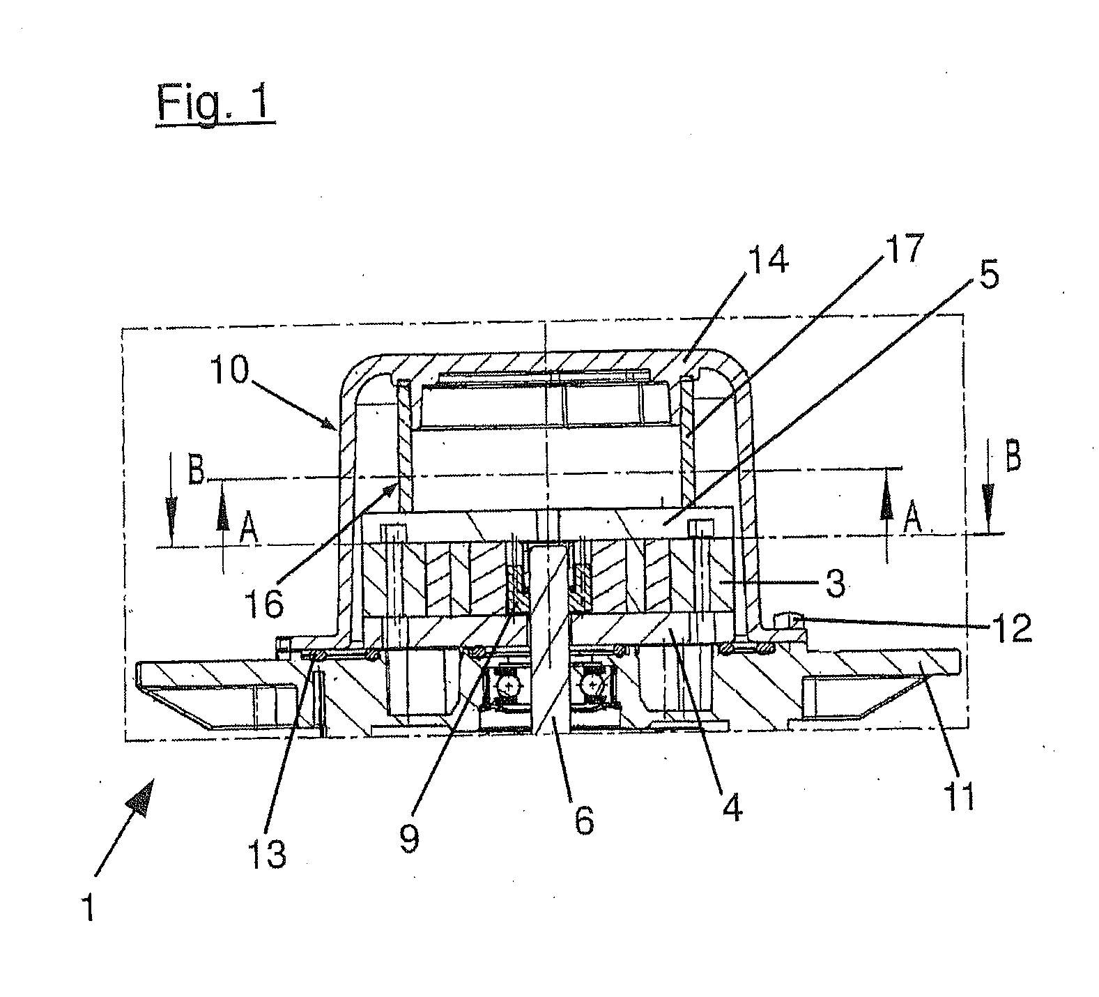
[0019]The basic structural shape and the basic functional principle of a vane cell pump 1 made according to a preferred embodiment of the present invention are known from the prior art and will be explained in more detail below. The vane cell pump 1 comprises an electrical drive unit that is housed in a housing of the vane cell pump 1 and has an electric motor with a motor shaft 6. The vane cell pump 1 (rotary vane pump) can be constructed, in particular, as a vacuum pump operating according to the so-called principle of positive displacement for generating a vacuum. Air or another fluid medium is taken in via a fluid inlet channel 15 constructed in the present case as a fluid inlet port when the vane cell pump 1 is operating and flows into a pump chamber 2 of the vane cell pump 1 and is compressed there.

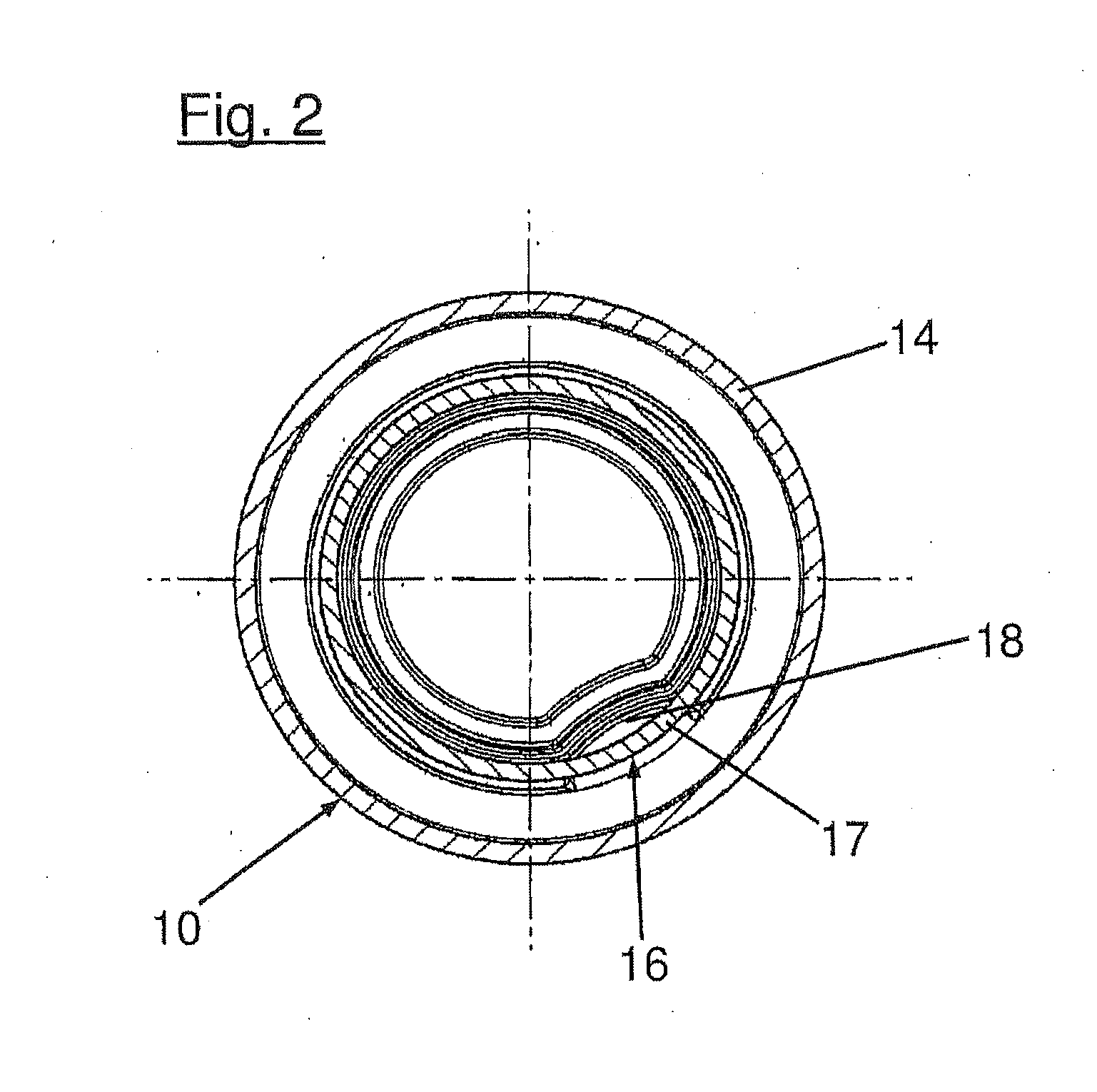
[0020]The pump chamber 2 comprises an interconnected base plate 4, a pump ring 3, and a cover plate 5. In this embodiment, the pump ring 3 has elliptical inner contours (visible, in...


PUM


Abstract

The invention relates to a vane cell pump comprising an electrical pump unit that has a pump chamber into and out of which a fluid can flow and also a rotor with a number of vanes to compress the fluid before flowing out from the pump chamber. The vane cell pump also comprises a sound-damping mechanism into which the fluid can flow after flowing through the pump chamber and that has a sound-damping cover attached to a part of the pump chamber and defining a sound-damping volume. A preliminary sound-damping mechanism with at least one preliminary sound-damping outlet from which the fluid can flow may be arranged within the sound-damping volume, wherein the preliminary sound-damping outlet has a cross-sectional profile tapering in the direction of fluid outflow.

Description

CROSS-REFERENCE TO RELATED APPLICATIONS[0001]This application claims priority to German Application No. 10 2009 056 010.6 filed on Nov. 26, 2009 and Application No. PCT / EP2010 / 068177 filed on Nov. 25, 2010.BACKGROUND[0002]The present invention relates to a vane cell pump comprising an electrical pump unit that has a pump chamber into and out of which a fluid can flow and also a rotor with a number of vanes that are arranged so that they can move in the rotor and by means of which the fluid can be compressed before flowing out from the pump chamber. The vane cell pump according to the invention also comprises a sound-damping mechanism into which the fluid can flow after flowing through the pump chamber and that has a sound-damping cover attached to a part of the pump chamber and defining a sound-damping volume, wherein a preliminary sound-damping mechanism with at least one preliminary sound-damping outlet from which the fluid can flow is arranged within the sound-damping volume.[000...

Claims


Application Information

Patent Timeline
Patent Type & Authority Applications(United States)
IPC IPC(8): F04C29/06
CPCF04C2/3446F04C15/0049F04C2270/13F04C2240/30F04C2250/102F04C15/06
Inventor HUSER, THEODORRUTHER, ALEXANDERSCHUBERT, UDO
Owner HELLA KG HUECK & CO
Why Eureka
Try Eureka